Powered air cleaning system and air cleaning method

a technology of air cleaning system and air cleaning method, which is applied in the direction of liquid degasification, auxillary pretreatment, separation processes, etc., can solve the problems of increasing the restriction of air flow through the filter, increasing the cost of operation, and reducing so as to reduce the operating performance of an associated device, efficiently remove debris, and reduce the effect of operating cos

Active Publication Date: 2008-11-18
SY KLONE
View PDF14 Cites 23 Cited by
  • Summary
  • Abstract
  • Description
  • Claims
  • Application Information

AI Technical Summary

Benefits of technology

[0003]Air intakes that centrifugally separate heavier-than-air particles from the air to be used in internal combustion engines, ventilation systems, and other apparatus that draw in air laden with debris, are known. The use of in-line filters in air delivery systems to clean the air is also, per se, known. However, air filters are subject to plugging by debris from the air passing through the filter, which eventually increases the restriction to air flow through the filter and decreases the operating performance of an associated device, such as an electronically controlled internal combustion engine being supplied with air through the filter. Frequent filter replacement and shorter service intervals may also be required, which increases the cost of operation. There is a need for an improved air cleaning system and air cleaning method which combine centrifugal separation and air filtration in a manner to efficiently remove debris from debris laden air while reducing or avoiding the aforementioned problems.
[0004]A powered air cleaning system according to the invention comprises a flow path extending through the system from an air inlet to a clean air outlet. A motor-driven fan is located along the flow path to draw particulate debris laden air into the inlet and rotate it about an axis to form a rotating flow that stratifies the debris laden air with the heaviest particles in the outermost orbits of the rotating flow. An ejector port is provided for ejecting particulate debris laden air from the stratified rotating flow in the system to the environment. An air filter is located within the rotating flow and across the flow path upstream of the clean air outlet for filtering air from the innermost orbits of the stratified rotating flow. According to the disclosed example embodiments of this invention, the filter is elongated in the direction of the axis about which the debris laden air is rotated. An outer peripheral surface of the filter within the rotating flow is swept by innermost orbits of the stratified rotating flow for minimizing debris buildup on the filter.
[0006]In one example embodiment, the ejector port of the system is located radially outward of the outermost orbits of the rotating flow, in the form of an ejector slot which extends the length of the air filter. This arrangement helps in subjecting the air filter to a slight positive pressure, reducing restriction to the engine or apparatus the air cleaning system is installed on and aiding the self cleaning of the air filter.

Problems solved by technology

However, air filters are subject to plugging by debris from the air passing through the filter, which eventually increases the restriction to air flow through the filter and decreases the operating performance of an associated device, such as an electronically controlled internal combustion engine being supplied with air through the filter.
Frequent filter replacement and shorter service intervals may also be required, which increases the cost of operation.

Method used


Image

  • Powered air cleaning system and air cleaning method
  • Powered air cleaning system and air cleaning method
  • Powered air cleaning system and air cleaning method

Examples


Embodiment Construction

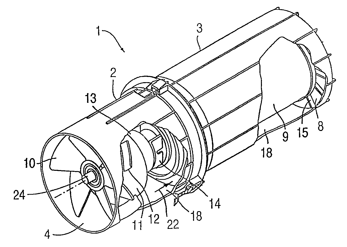
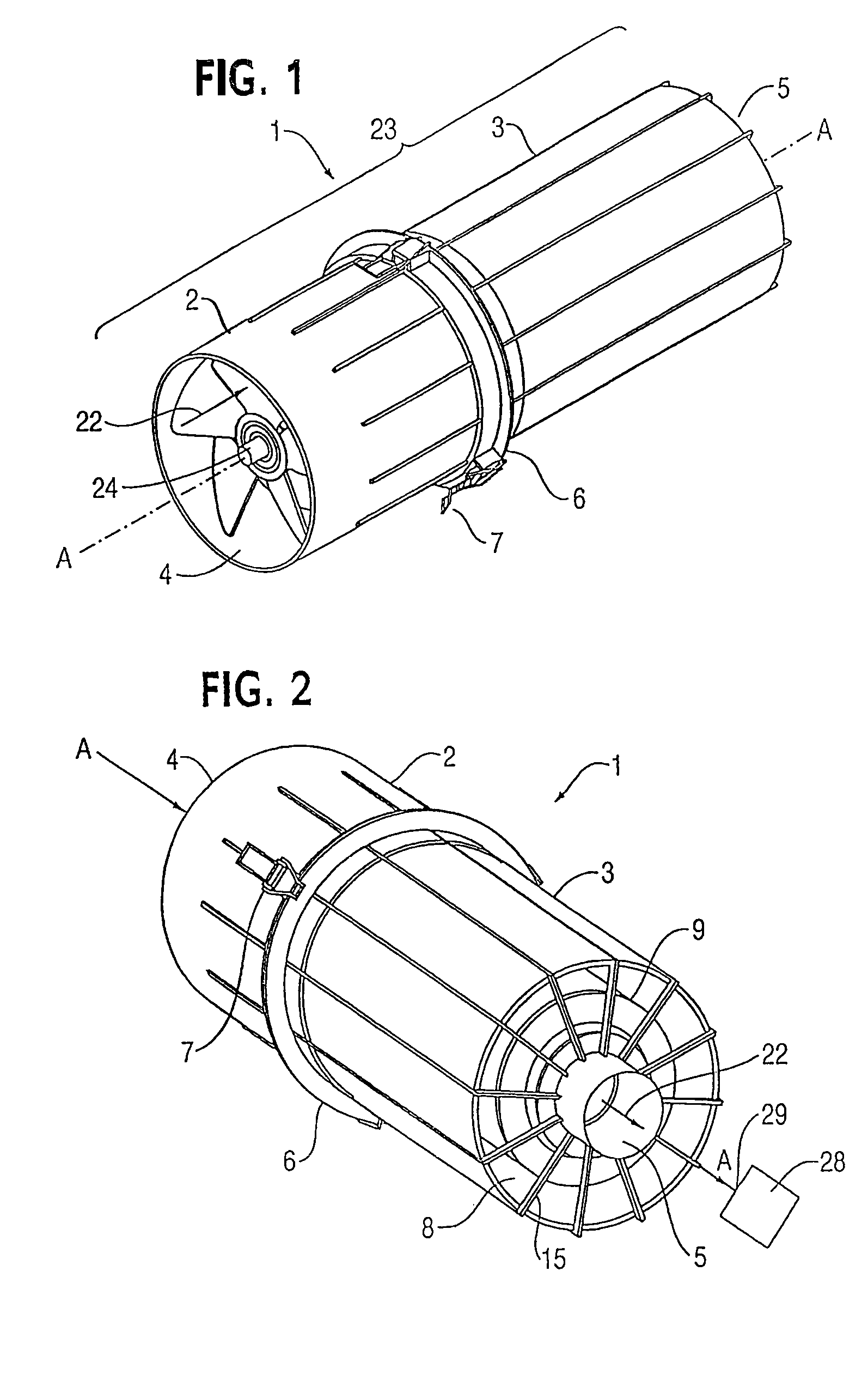
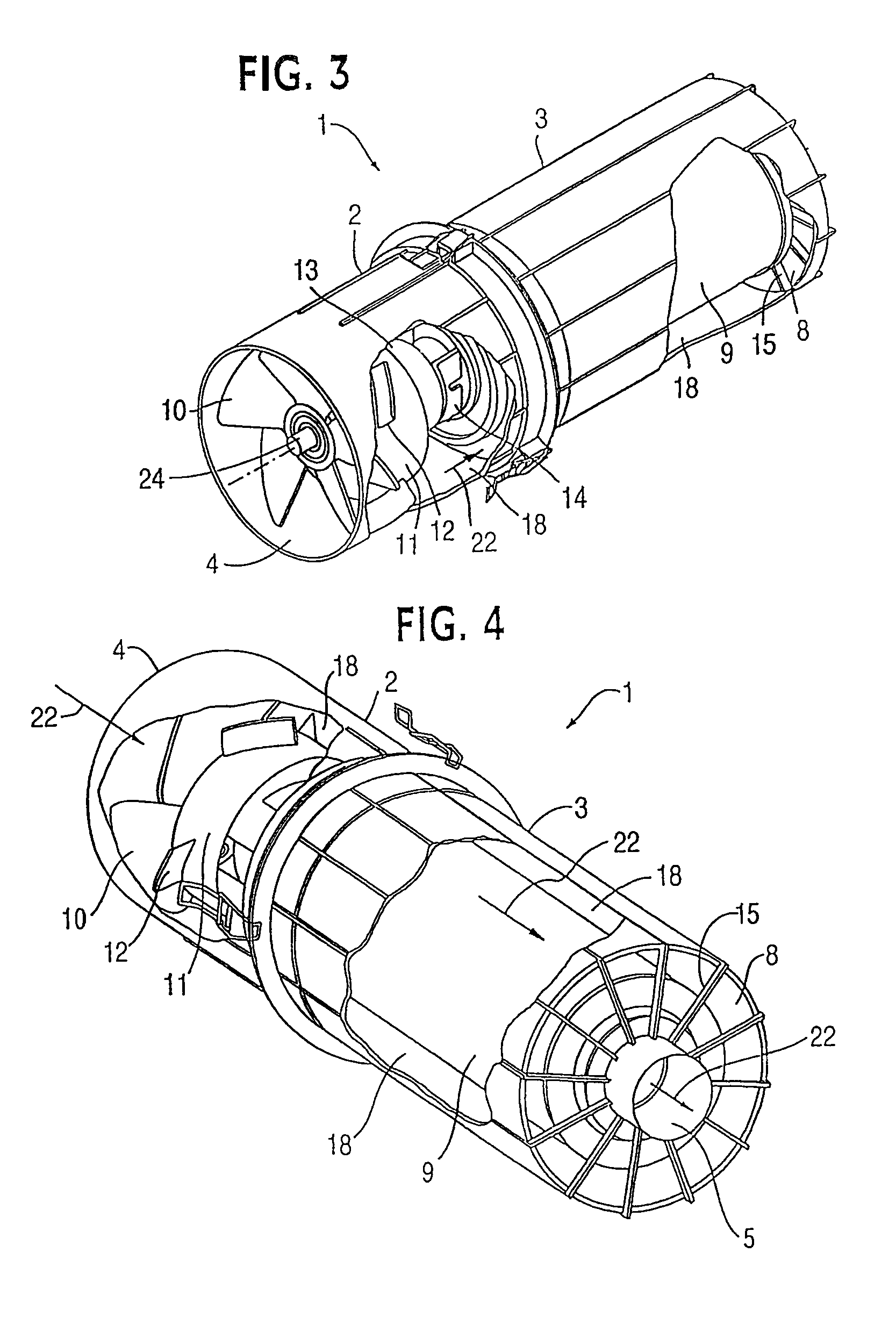
[0025]Referring now to the drawings, a powered air cleaning system or apparatus 1, FIGS. 1-6, according to a first example embodiment is shown connected to the air intake 29 of a device 28, such as an internal combustion engine or other device requiring a supply of clean air, as shown schematically in FIG. 2. The system comprises a flow path 22 extending through the system from an air inlet 4 to a clean air outlet 5 which supplies clean air to the air intake 29 of device 28. The flow path is located within a generally cylindrical housing 23 of the system. Housing 23 is formed by two detachable components—motorized fan housing 2 and filter housing 3 which are detachably connected to one another at a service flange assembly 6 by joining clips 7, see FIG. 7. For this purpose each of the housings 2 and 3 has a joining flange, 16 and 17, respectively. The housings 2 and 3 are shown detached from one another in FIG. 6 and shown separately in FIGS. 8 and 9, and 12 and 13, respectively.

[002...


PUM

PropertyMeasurementUnit
lengthaaaaaaaaaa
velocityaaaaaaaaaa
pressureaaaaaaaaaa

Abstract

A powered air cleaning system (31) and air cleaning method are disclosed. The system comprises a flow path (22) extending through the system from an air inlet (4) to a clean air outlet (5). A motor-driven fan (24) located along the flow path draws particulate debris laden air into the inlet and rotates it about an axis (A-A) to form a rotating flow that stratifies the debris laden air with the heaviest particles in the outermost orbits of the rotating flow. An ejector port (33) is provided for ejecting particulate debris laden air from the stratified rotating flow in the system to the environment. An air filter (9) located within the rotating flow and across the flow path upstream of the outlet filters air from the innermost orbits of the stratified rotating flow. The motor-driven fan is operated to maintain a positive air pressure in the system on the filter even with cyclic air flow demands so that the rotating air flow continually sweeps the outside surface of the air filter to minimize buildup of debris on the filter.

Description

RELATED APPLICATIONS[0001]This application is a U.S. national stage application under 35 U.S.C. §371 of pending international application number PCT / US03 / 10238 filed Apr. 4, 2003, which in turn is a continuation in part application of international application PCT / US02 / 33220 filed Oct. 18, 2002 which designated the U.S. and claimed priority of U.S. provisional application 60 / 329,748 filed Oct. 18, 2001.TECHNICAL FIELD[0002]The present invention is directed to an improved powered, atmospheric ejective, air cleaning system and air cleaning method for efficiently removing debris from debris laden air to supply clean air to a device with which the system is used. For example, the invention is useful in connection with total air flow applications such as ventilation systems, as a fixed air flow provider for heat exchangers and heating and air conditioning systems, and with devices having a variable air flow demand, particularly internal combustion engines which exert a variable vacuum on...

Claims


Application Information

Patent Timeline
Patent Type & Authority Patents(United States)
IPC IPC(8): B01D45/12B01D46/00B01D50/00
CPCB01D45/12B01D50/002B01D50/20
Inventor MOREDOCK, JAMES G.EHRENBERG, ERIC L.
Owner SY KLONE
Why Eureka
Try Eureka