
Apparatus for and method of bonding nano-tip using electrochemical etching

a nano-tip and electrochemical etching technology, applied in the field of apparatus for and a method of bonding a nano-tip using electrochemical etching, can solve the problems of unnecessary amorphous carbon deposited on the surface of a carbon nano-tube, needing additional processes, and achieving good bonding stability

Inactive Publication Date: 2008-11-18
KOREA ADVANCED INST OF SCI & TECH
View PDF0 Cites 2 Cited by
  • Summary
  • Abstract
  • Description
  • Claims
  • Application Information

AI Technical Summary

Benefits of technology

"The present invention provides an apparatus and method for bonding a nano-tip using electrochemical etching. The apparatus includes a glass plate, an electrolytic solution, a base material, a carbon nano-tube, and a power supply. The method involves attaching the carbon nano-tube to the base material, applying an electric power to the electrolytic solution, moving the base material in one direction, melting the adhesive with the heat generated by resistance, and solidifying the melted adhesive to bond the carbon nano-tube. The invention provides a good bonding stability between the carbon nano-tube and the base material, as well as for a separate nano-probe. The apparatus and method can be used for various applications such as sensing and electron microscopy observation."

Problems solved by technology

In the above conventional technique, however, an additional process is needed to improve the bonding stability, and high-priced equipment such as the scanning electron microscope is necessarily required.
In addition, unnecessary amorphous carbon is deposited on the surface of a carbon nano-tube.

Method used


Image

  • Apparatus for and method of bonding nano-tip using electrochemical etching
  • Apparatus for and method of bonding nano-tip using electrochemical etching
  • Apparatus for and method of bonding nano-tip using electrochemical etching

Examples


Embodiment Construction

[0024]The preferred embodiments of the invention will be hereafter described in detail, with reference to the accompanying drawings.

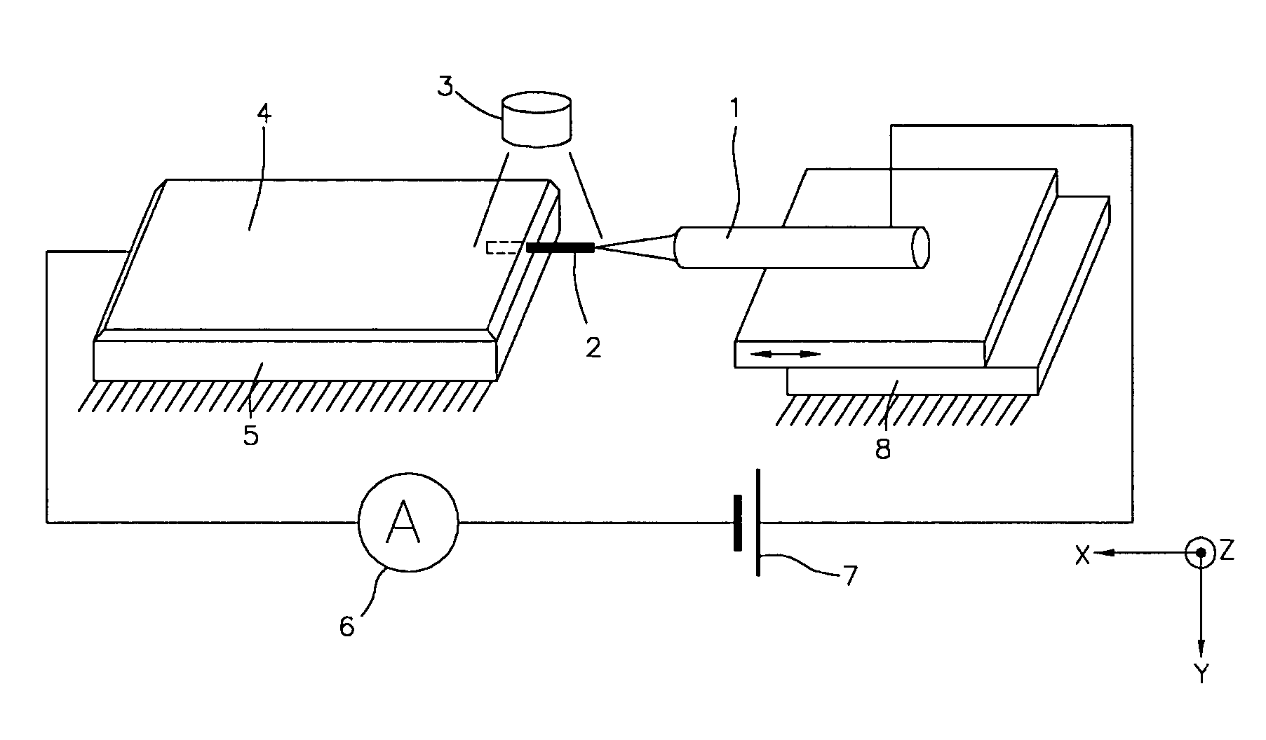
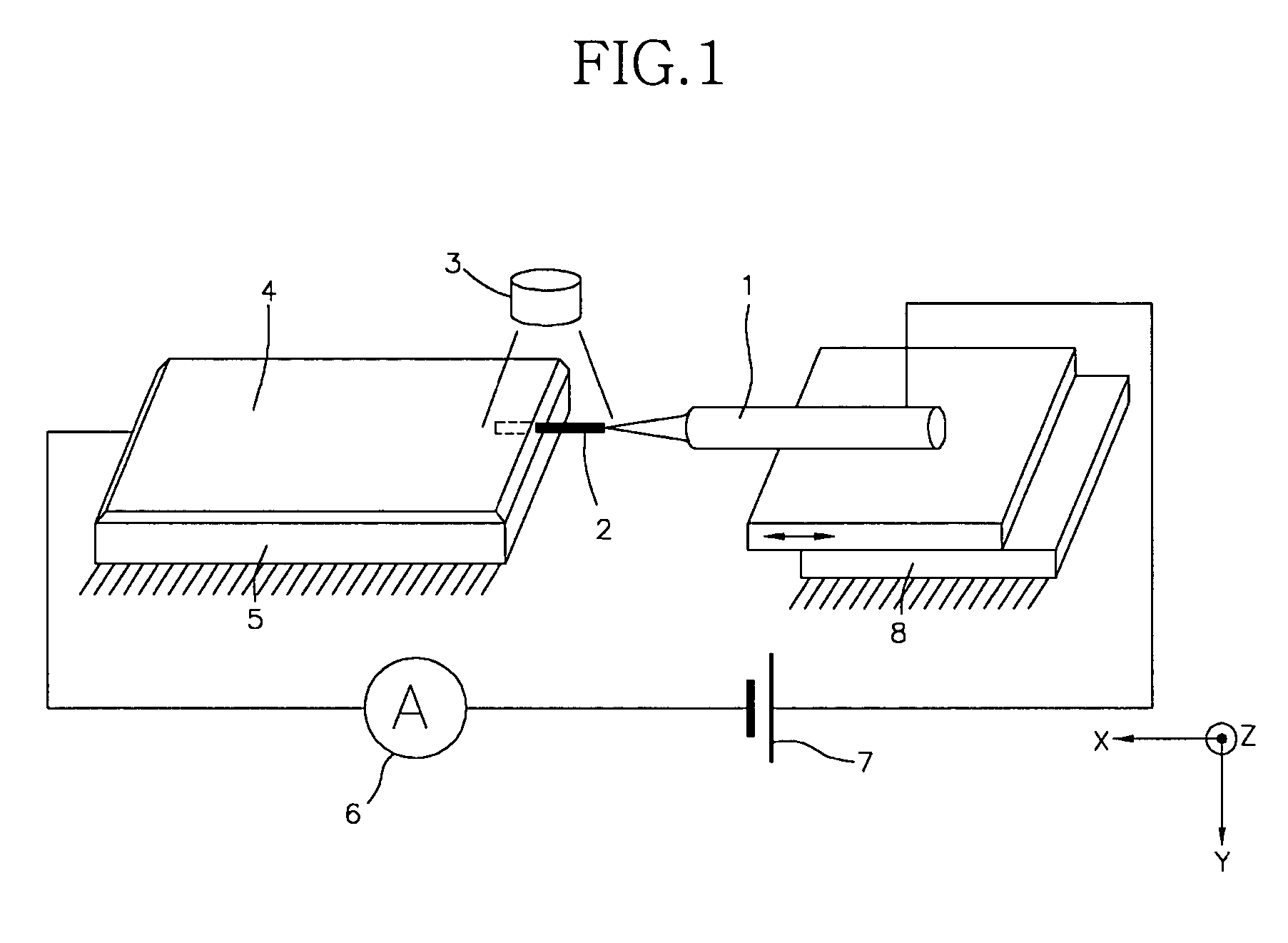
[0025]FIG. 1 is a schematic perspective view of a nano-tip bonding apparatus using electrochemical etching according to an embodiment of the invention. Referring to FIG. 1, the nano-tip bonding apparatus of the invention comprises generally a glass plate 5 and a nano stage 8.

[0026]The glass plate 5 is electrically non-conductive and placed horizontally. The glass plate 5 has a flat top surface. On the top surface of the glass plate 5 is placed an electrolytic solution 4 in a certain desired thickness. The electrolytic solution 4 is not retained in a separate container, but held in place by the surface tension on top of the glass plate 5. An electrode is immersed in one side of the electrolytic solution 4, to which thereby a direct electric power can be applied.

[0027]On top of the nano stage 8 is placed a base material 1. The nano stage 8 is configured s...


PUM

PropertyMeasurementUnit
surface tensionaaaaaaaaaa
conductivityaaaaaaaaaa
electric poweraaaaaaaaaa

Abstract

Disclosed herein are an apparatus for and a method of bonding a nano-tip using electrochemical etching, in which a good bonding stability can be provided. The nano-tip bonding apparatus comprises a glass plate having a top surface of a certain desired area. An electrolytic solution having conductivity is placed on the top surface of the glass plate by means of surface tension. Means for moving reciprocally a base material having conductivity in opposite direction is provided. A carbon nano-tube is adhered to a pointed tip of the base material by means of an adhesive. An end portion of the carbon nano-tube is to be immersed in the electrolytic solution. A power supply is provided for applying an electric power to the electrolytic solution and the base material.

Description

BACKGROUND OF THE INVENTION[0001]1. Field of the Invention[0002]The present invention relates to an apparatus for and a method of bonding a nano-tip using electrochemical etching, in which a good bonding stability can be provided.[0003]2. Background of the Related Art[0004]In order to handle a nano-sized object, generally the tools therefor must also have a resolution on the order of nanometers. It is therefore necessary in the nano industry to develop a nano-probe (a micro tip).[0005]A suitable solution to improve the bonding stability of a carbon nano-tube has rarely been proposed. Conventionally, first, a nano probe is fabricated and then put inside a scanning electron microscope. Thereafter, electron beam is radiated on the bonding area and at this time amorphous carbon inside the scanning electron microscope is vapor-deposited in the bonding area, thereby enhancing the bonding force.[0006]In the above conventional technique, however, an additional process is needed to improve t...

Claims


Application Information

Patent Timeline
Patent Type & Authority Patents(United States)
IPC IPC(8): B32B41/00
CPCB82Y15/00B82Y30/00B82Y35/00G01Q70/12Y10S977/876Y10S977/851Y10S977/882Y10S977/856Y10S977/896B82B3/00H01J37/28
Inventor KIM, SOO HYUNLEE, JUN SOKCHOI, JAI SEONGKANG, GYUNG SOO
Owner KOREA ADVANCED INST OF SCI & TECH
Learn More