Leaky SAW resonator and method

a technology of surface acoustic wave and saw resonator, which is applied in piezoelectric/electrostrictive/magnetostrictive devices, piezoelectric/electrostriction/magnetostriction machines, electrical equipment, etc., can solve the problems of notches or ripples in the pass band, radiation loss of leaky surface acoustic wave resonators, and reduce the usable bandwidth and quality factor, q, of filters

Active Publication Date: 2008-11-18
TRIQUINT
View PDF7 Cites 45 Cited by
  • Summary
  • Abstract
  • Description
  • Claims
  • Application Information

AI Technical Summary

Benefits of technology

[0011]Embodiments of the present invention reduce radiation loss and its effects in a leaky SAW resonator. Embodiments of the present invention improve the Q of the resonator to enhance the filter performance. One embodiment may comprise a SAW filter having a piezoelectric substrate and transversely opposing bus bars longitudinally disposed on a surface with a plurality of grating pads transversely extending inwardly along the surface from each of the bus bars, and interdigital transducer electrodes disposed along a longitudinal axis on the surface for defining an acoustic aperture across overlapping interdigital transducer electrodes within a transverse dimension thereof, wherein each of the plurality o

Problems solved by technology

It is well known that leaky surface acoustic wave resonators exhibit radiation losses over a range of frequencies.
When configured as a band pass filter, this radiation of leaky waves into the bus bars is manifested as extra insertion loss at certain frequencies, often causing notches or ripples in the pass band.
Depending upon the frequency dependence of the radiation of the leaky waves, the performance degradation may be pronounced near the pass band center or it may occur mostly near one or both pass band edges, thus reducing the usable bandwidth and quality factor, Q, of the filter.
Radiation in leaky surface acoustic wave resonators is difficult to accurately model and is, there

Method used


Image

  • Leaky SAW resonator and method
  • Leaky SAW resonator and method
  • Leaky SAW resonator and method

Examples


Embodiment Construction

[0035]The present invention will now be described more fully with reference to the accompanying drawings in which alternate embodiments of the invention are shown and described. It is to be understood that the invention may be embodied in many different forms and should not be construed as limited to the illustrated embodiments set forth herein. Rather, these embodiments are provided so that this disclosure may be thorough and complete, and will convey the scope of the invention to those skilled in the art.

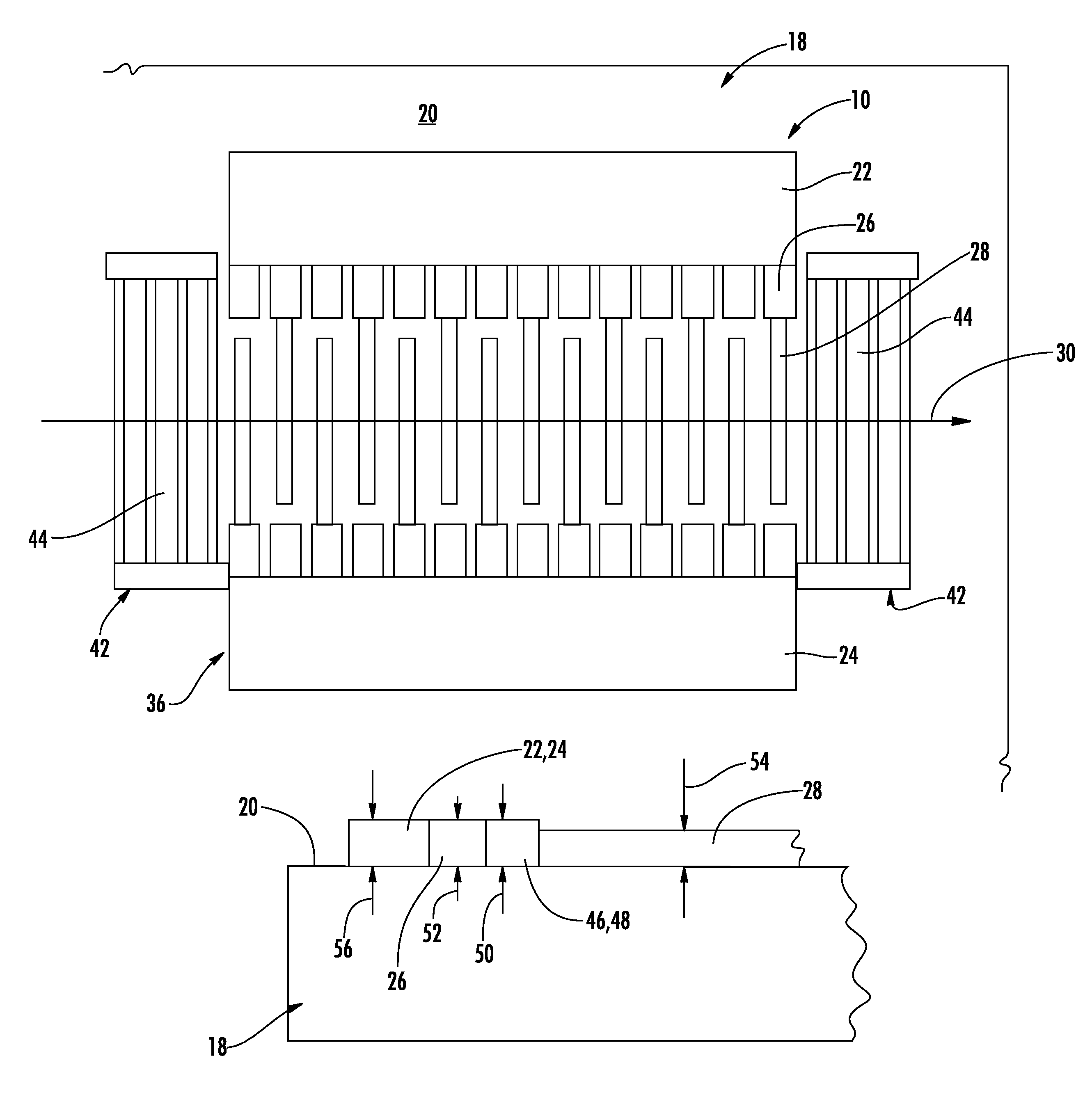
[0036]With reference now to FIGS. 7 and 8, one embodiment of the present invention includes a SAW resonator 10 that is operable with a SAW ladder filter 12 having at least one resonator in a series arm 14 and at least one resonator in a parallel arm 16 to form the ladder filter. With continued reference to FIG. 7, the resonator 10 comprises a piezoelectric substrate 18 having a surface 20 for supporting SAW propagation. Transversely opposing first and second bus bars 22, 24 are lo...


PUM


Abstract

A SAW ladder filter includes grating pads extending from opposing bus bars and interdigital transducer electrodes extending from the grating pads for defining an acoustic aperture. The metalization ratio for the grating pads is greater than that for the interdigital transducer electrodes. Reflector electrodes are disposed on opposing longitudinal sides of the interdigital transducer electrodes. Operation of the filter results in a velocity of the SAW along the grating pads slower than a SAW velocity along the plurality of interdigital transducer electrodes, thus producing a wave guiding effect for optimizing SAW propagation within the acoustic aperture. The grating pads may be longitudinally offset from cooperating interdigital transducer electrodes using minor bus bars.

Description

CROSS-REFERENCE TO RELATED APPLICATION[0001]This application claims the benefit of U.S. Provisional Application No. 60 / 663,828 for “Leaky SAW Resonator and Method” having filing date Mar. 21, 2005, the disclosure of which is incorporated herein by reference in its entirety, all being commonly owned.FIELD OF INVENTION[0002]The present invention generally relates to surface acoustic wave devices, and particularly to surface acoustic wave resonators having improved energy characteristics.BACKGROUND OF THE INVENTION[0003]Surface Acoustic Wave (SAW) resonators have been widely applied to the design of surface acoustic wave filters for use in many different communication systems. FIG. 1 depicts a typical SAW resonator, its symbol, and equivalent circuit. The SAW resonator, which generally comprises a transducer embedded between two reflectors, may be fabricated on a single crystal piezoelectric substrate of lithium niobate or lithium tantalate. The transducer is typically a two terminal d...

Claims


Application Information

Patent Timeline
IPC IPC(8): H03H9/145H03H9/25H03H9/64
CPCH03H9/02543H03H9/02944H03H9/02992H03H9/1452
Inventor ABBOTT, BENJAMIN P.CARON, JOSHUA J.GARRIS, STEVEN
Owner TRIQUINT
Why Eureka
Try Eureka