Blazed diffractive optical element and projection objective for a microlithographic projection exposure apparatus

a diffractive optical element and exposure apparatus technology, applied in the field of diffractive optical elements, can solve the problems of not being able to achieve quite such high diffraction efficiency, and achieve the effect of achieving diffraction efficiency in this case commensurate with the amount of material produced

Inactive Publication Date: 2008-11-18
CARL ZEISS SMT GMBH
View PDF16 Cites 5 Cited by
  • Summary
  • Abstract
  • Description
  • Claims
  • Application Information

AI Technical Summary

Benefits of technology

[0011]It is therefore an object of the present invention to provide a diffractive optical element which is simple to produce and has a very high diffraction efficiency.
[0017]It is however easier to produce substitute structures having a blaze profile which, using a step curve, approximates a conventional blaze profile with a continuously rising blaze edge and a back edge falling steeply, in particular perpendicularly to the base surface. The diffraction efficiency is in this case commensurately greater as the step curve approximates the ramp shape better. The substitute structure then has a rectangular profile and may thus also be regarded as a binary substructure which is normal per se, but which is flatter and / or wider than each of the substrates which are replaced by the substitute structure.

Problems solved by technology

Although it is not possible to achieve quite such high diffraction efficiencies as with complete substructures, i.e. ones obtained per se computationally, the achievable diffraction efficiency is nevertheless significantly higher than when the substructures with a high aspect ratio are entirely omitted because of the production difficulties.

Method used


Image

  • Blazed diffractive optical element and projection objective for a microlithographic projection exposure apparatus
  • Blazed diffractive optical element and projection objective for a microlithographic projection exposure apparatus
  • Blazed diffractive optical element and projection objective for a microlithographic projection exposure apparatus

Examples


Embodiment Construction

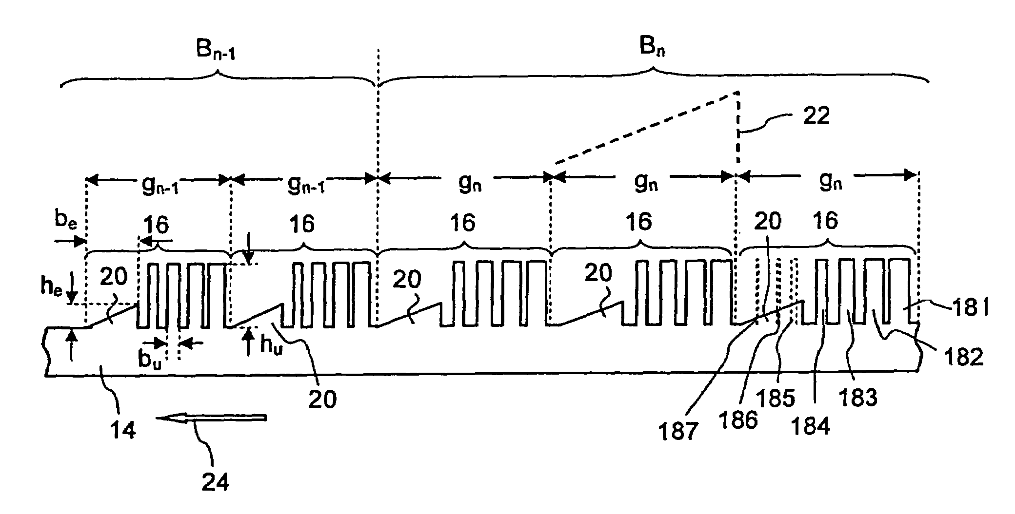
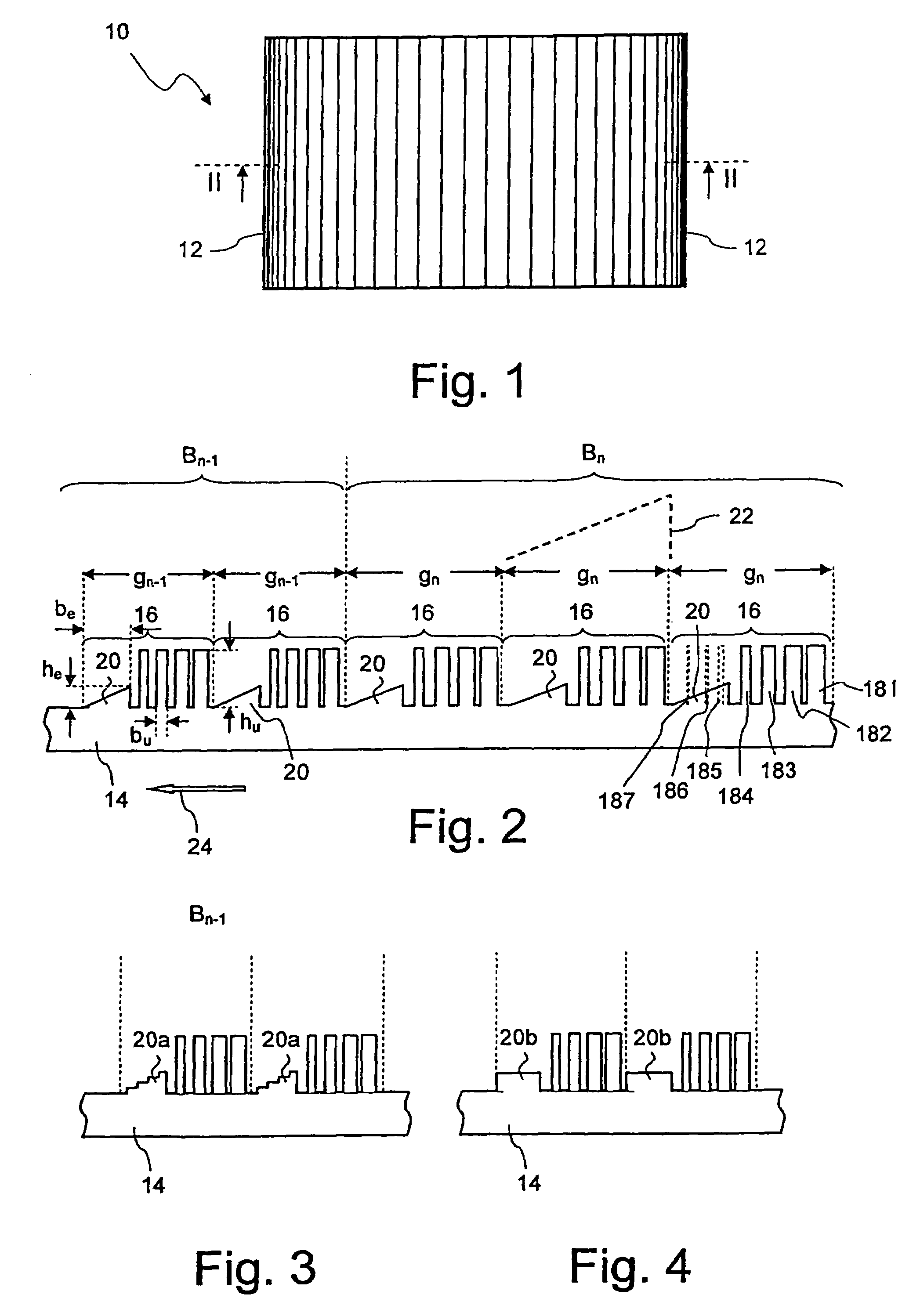
[0026]A first exemplary embodiment of a diffractive optical element, denoted overall by 10, is shown in FIG. 1 by a schematic representation in plan view, which is not true to scale, and in FIG. 2 as details in a section along the line II-II. The diffractive optical element 10 is designed as a rectangular linear blaze grating, the grating constant g of which decreases sectionally towards the transverse sides 12. FIG. 1 indicates the decrease in the grating constant by the vertical lines which become denser towards the transverse sides 12.

[0027]The diffractive optical element 10 comprises a multiplicity of diffraction structures 16 applied on a support 14, which are subdivided into a plurality of regions with respectively equal grating constants. The enlarged sectional representation of FIG. 2 represents in all two of these regions Bn−1 and Bn, within which the grating constant gi is respectively constant. The grating constants gi decrease from right to left in the representation of ...


PUM

PropertyMeasurementUnit
aspect ratioaaaaaaaaaa
structuresaaaaaaaaaa

Abstract

A diffractive optical element has a support and a plurality of diffraction structures. The latter are applied on the support and are binary blazed by being split into substructures so that the aspect ratio of the substructures varies locally within an individual diffraction structure. One or more substructures with a large aspect ratio inside an individual diffraction structure are replaced by at least one substitute structure whose aspect ratio is less than that of the replaced substructures.

Description

CROSS-REFERENCE TO RELATED APPLICATIONS[0001]This application is a continuation of International Application PCT / EP2004 / 004637, with an international filing date of May 3, 2004 and claiming priority of German Patent Application DE 103 22 238 filed May 17, 2003. The full disclosures of both earlier applications are incorporated herein by reference.BACKGROUND OF THE INVENTION[0002]1. Field of the Invention[0003]The invention relates to a diffractive optical element having a support and a plurality of diffraction structures which are applied thereon and are binary blazed by being split into substructures so that the aspect ratio of the substructures varies locally within an individual diffraction structure.[0004]2. Description of Related Art[0005]Diffractive optical elements with locally varying grating constants have found many applications in optics. Diffractive optical elements are used, for example, to generate wavefront profiles which cannot—or only with great difficulty—be achiev...

Claims


Application Information

Patent Timeline
Patent Type & Authority Patents(United States)
IPC IPC(8): G02B5/18G02B27/44G03F7/20
CPCG02B5/1838G02B5/1842G03F7/70316G02B27/4277G02B27/4205
Inventor KLEEMANN, BERND
Owner CARL ZEISS SMT GMBH
Why Eureka
Try Eureka