Methods and apparatus for detection of signal timing

a signal timing and detection method technology, applied in the direction of instruments, navigation instruments, amplitude demodulation, etc., can solve the problems of reducing the accuracy and operability of such position location techniques, affecting the accuracy of signal timing, so as to reduce the amplitude of other samples and reduce the amplitud

Active Publication Date: 2008-11-18
HARRIS GLOBAL COMMUNICATIONS INC
View PDF35 Cites 50 Cited by
  • Summary
  • Abstract
  • Description
  • Claims
  • Application Information

AI Technical Summary

Benefits of technology

[0016]The apparatus can further include a filter that emphasizes one or more signal peaks in the correlated signal, wherein the signal peaks correspond to potential signal paths of the received signal. For example, the filter can include a coarse filter and a fine filter that filter the correlated signal by masking portions of the correlated signal outside the vicinity of signal peaks, wherein the fine filter has a narrower time-domain filtering win

Problems solved by technology

The accuracy and operability of such position location techniques can be severely degraded in the presence of multipath interference caused by a signal traveling from a transmitter to the receiver along plural different paths, including a direct path and multiple, longer paths over which the signal is reflected off objects or other signal-reflective media.
Unfortunately, multipath interference can be most severe in some of the very environments in which position location techniques would have their greatest usefulness, such as in urban environments and/or inside buildings, since artificial structures create opportunities for signals to be reflected, thereby causing signals to arrive at the receiver via a number of different paths.
In a position determining system relying on precise measurements of direct-path signal propagation time to determine range, erroneously interpreting a multipath signal as the direct path signal can drastically degrade performance.
In particular, a multipath signal may result in a severely erroneous range measurement; nevertheless, if the multipath signal has a relatively high signal-to-noise ratio, the erroneous range measurem

Method used


Image

  • Methods and apparatus for detection of signal timing
  • Methods and apparatus for detection of signal timing
  • Methods and apparatus for detection of signal timing

Examples


Embodiment Construction

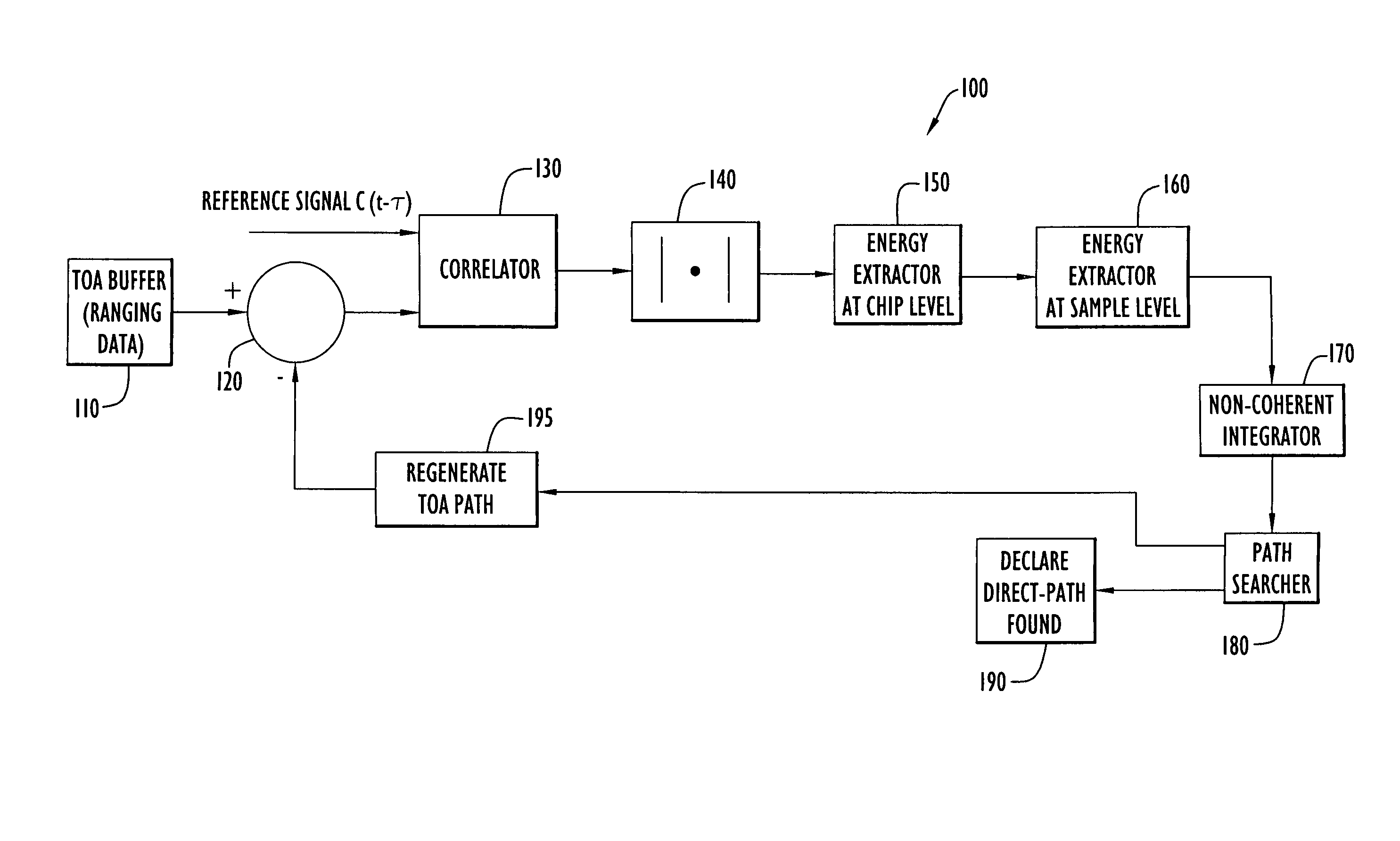
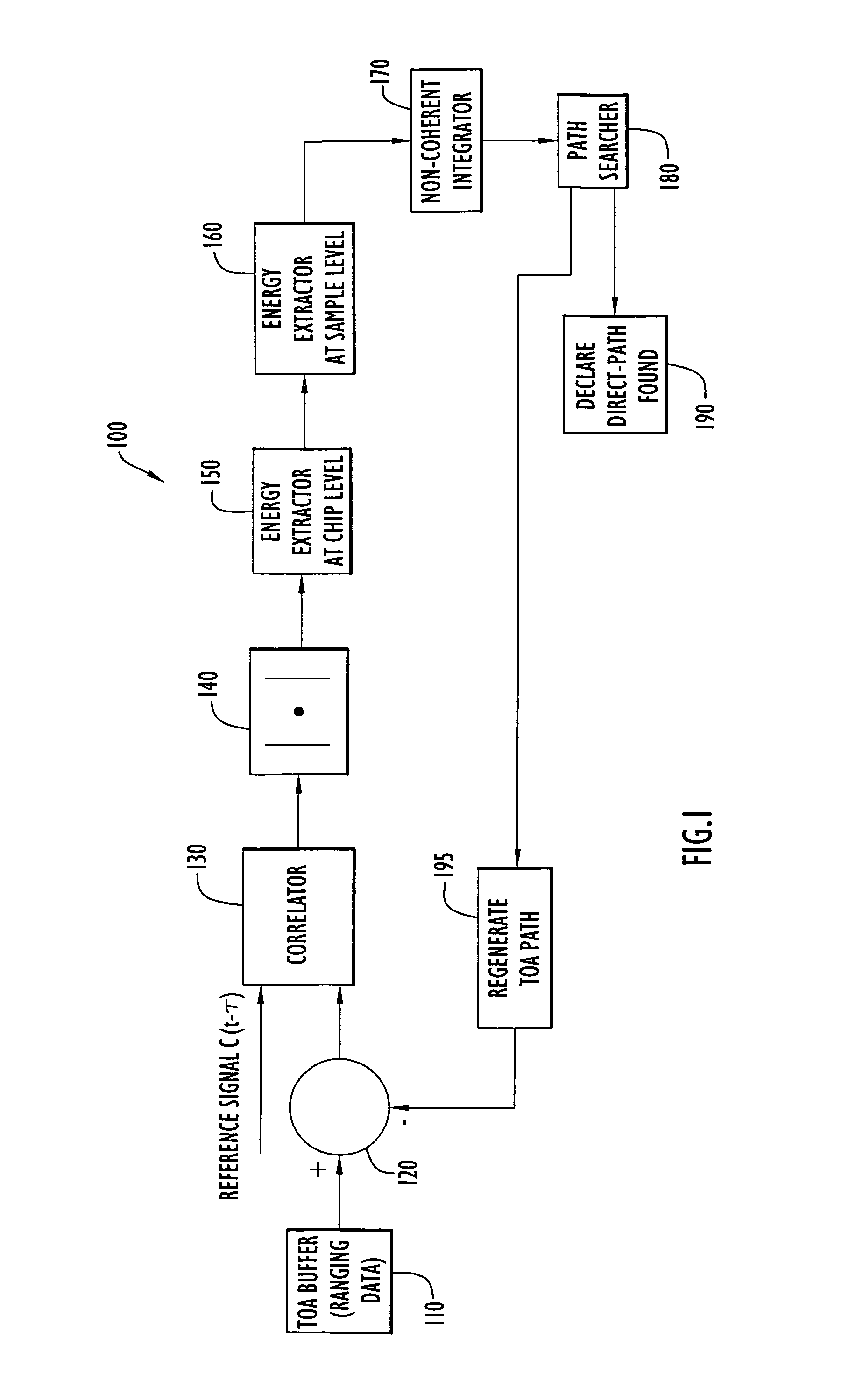
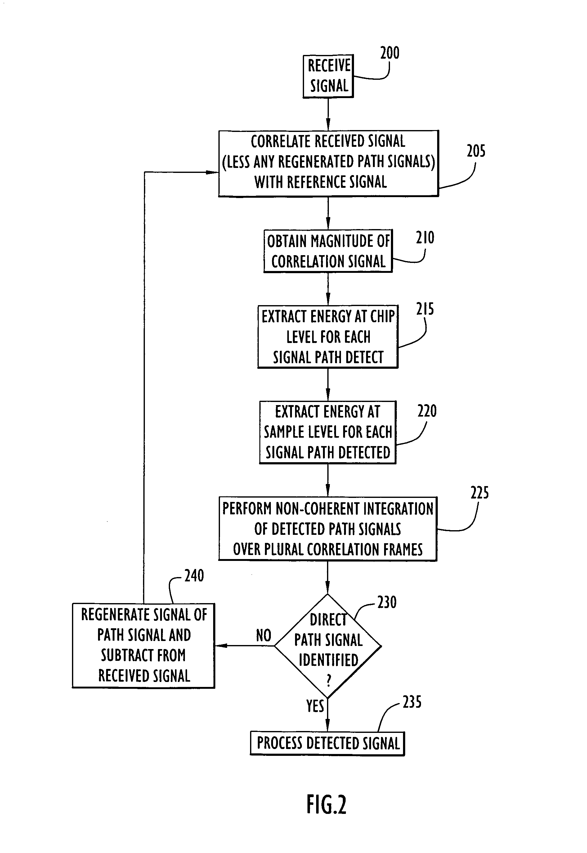
[0029]The invention overcomes the aforementioned problem of strong multipath signals by iteratively subtracting the estimated strong-path signals from a received signal at the input of a correlator. When M number of signals from dominant paths are present in the correlator, each path's signal can be accurately estimated with its magnitude and phase, and the contributions of these signals to the total received signal can be completely eliminated. As a result, only the desired path signal such as the direct path is left at the correlator output.

[0030]Detecting an individual path among many paths is achieved by utilizing the symmetric property of the auto-correlation function of a spread-spectrum waveform. The triangular shape of the correlation function provides the opportunity to process the shape to extract the desired path by enhancing its correlation value at the path position and at the same time to suppress the other paths' interference. However, a simple one-stage processing of...


PUM


Abstract

A technique is described for determining the timing of a received signal that includes one or more time-delayed versions of a reference signal traveling over respective different signal paths. The technique includes correlating the received signal with the reference signal to produce a correlated signal; determining whether the correlated signal includes a signal peak that corresponds to the direct path of the received signal; and iterative repeating these operations until a signal peak is determined to correspond to the direct path of the received signal. In each successive iteration, the reference signal corresponding to at least the greatest signal peak in the correlated signal is regenerated, and contributions from each regenerated reference signal are removed from the received signal prior to correlating the received signal in the next iteration.

Description

BACKGROUND OF THE INVENTION[0001]1. Field of the Invention[0002]The present invention relates to methods and apparatus for measuring signal timing and, more particularly, to techniques for accurately identifying a direct path signal in the presence of multipath signals.[0003]2. Description of the Related Art[0004]Accurate determination of signal timing is desirable in a wide variety of communication and navigation applications where precise, reliable signal reception is desired. For example, U.S. Pat. Nos. 6,453,168 and 6,801,728, the disclosures of which are incorporated herein by reference in their entireties, disclose state-of-the-art position location and communication systems that provide accurate, reliable three-dimensional position determination of a handheld or portable, spread spectrum communication device within milliseconds without interruption of voice or data communications. Using spread spectrum waveforms and processing techniques, the system is capable of determining ...

Claims


Application Information

Patent Timeline
IPC IPC(8): H04L27/06G01S19/22G01S1/00G01S5/02
CPCG01C21/206G01S5/0215G01S19/22H04B1/7075H04B2201/70715G01S5/0218
Inventor LI, DONMCCRADY, DENNIS D
Owner HARRIS GLOBAL COMMUNICATIONS INC
Why Eureka
Try Eureka