Nuclear fuel assembly control rod drive thimble to bottom nozzle connector

a technology of fuel assembly and control rod, which is applied in the direction of screws, nuclear elements, greenhouse gas reduction, etc., can solve the problems of increasing power output, limited maximum reactor operating power, and limited power output of nuclear reactor, so as to facilitate rework and inspection, the effect of easy implementation

Active Publication Date: 2008-11-18
WESTINGHOUSE ELECTRIC CORP
View PDF9 Cites 41 Cited by
  • Summary
  • Abstract
  • Description
  • Claims
  • Application Information

AI Technical Summary

Benefits of technology

[0010]Thus, in view of the above mentioned design considerations, the present invention provides a nuclear reactor fuel assembly with an improved control rod guide thimble to lower nozzle connection that has fewer components and is easier to implement, re-work and inspect.

Problems solved by technology

Therefore, the maximum reactor operating power is limited by some enthalpy and / or temperature value in the reactor core.
The reactivity and, in-turn, the power output of a nuclear reactor is limited by the amount of structural material in the reactor core, as the structural material parasitically absorbs neutrons which could otherwise be used in the fission process.
Furthermore, a reduction of the structural material in the fuel assembly reduces the pressure drop and thereby increases the power output.
Some of these costs are associated with the fixed components of the fuel assembly forming the fuel assembly skeleton.
The welding procedure requires the ability of a skilled operator and inspection of the finished product is very difficult because of the deep recess in the bottom nozzle leg counterbore.
This weld procedure is performed after the fuel assembly is loaded with fuel rods, thus raising the level of difficulty in completing the task as well as increasing the difficulty of recovery should an improper weld be performed.

Method used


Image

  • Nuclear fuel assembly control rod drive thimble to bottom nozzle connector
  • Nuclear fuel assembly control rod drive thimble to bottom nozzle connector
  • Nuclear fuel assembly control rod drive thimble to bottom nozzle connector

Examples


Embodiment Construction

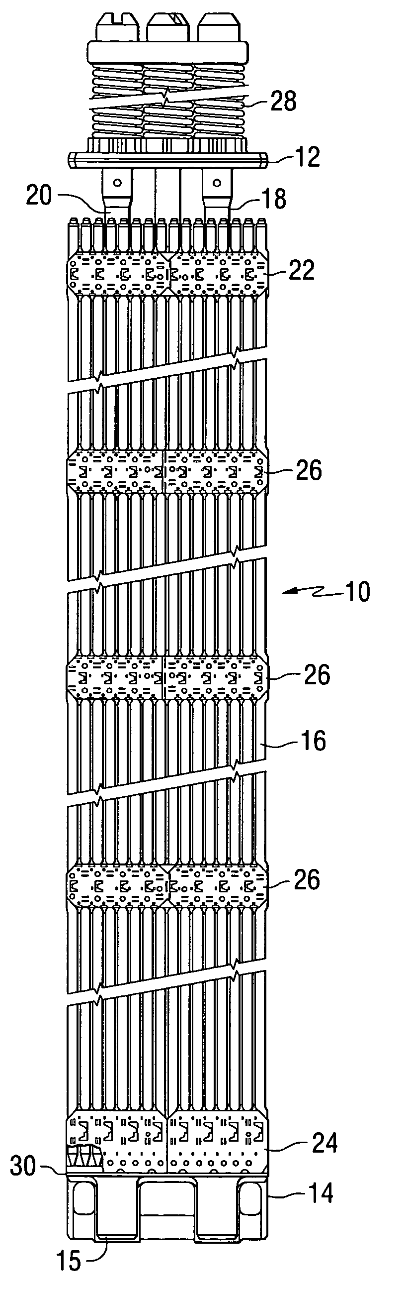
[0019]Referring to the drawings, particularly to FIG. 1, the fuel assembly 10 is shown comprising an upper end structure or nozzle 12, a lower end structure or nozzle 14, a generally square array of substantially parallel elongated fuel elements or rods 16, a plurality of elongated hollow tubular members 18 containing control elements 20 strategically located among the array of fuel element 16, a top grid member 22, a bottom grid member 24, and a plurality of intermediate grid members 26 longitudinally spaced along the tubular members 18, which are also referred to as control rod guide thimbles or guide tubes. An instrumentation tube is located at the center of the fuel assembly, although not shown.

[0020]As shown in FIG. 1 the upper end nozzle 12 is a generally square shaped plate having elongated coil springs extend upwardly in an axial direction. In the reactor core the springs 28 are seated against the upper core plate and function to hold down the fuel assembly while permitting ...


PUM


Abstract

A secure connection between the bottom nozzle of a nuclear fuel assembly and the control rod guide thimbles having two or four crimped pockets in the side wall of a bottom nozzle leg counterbore which are formed by drilling two or four blind holes through the top surface of the bottom nozzle. After attaching the bottom nozzle to the fuel assembly with a crimp bolt a pneumatic tool is then inserted into a flanged cup feature on the crimp bolt head and the flanged portion of the cup feature of the crimp bolt is deformed into the crimp pockets. The crimp pockets are contained within the leg counterbore and prevent the screw from rotating or falling out of the assembly in the event of preload loss or screw fracture.

Description

BACKGROUND OF THE INVENTION[0001]1. Field of the Invention[0002]The present invention relates generally to fuel assemblies for nuclear reactors and, more particularly, is directed to an improved connection between the lower nozzle of the fuel assemblies and the control rod guide thimbles.[0003]2. Background Information[0004]In most nuclear reactors the core portion is comprised of a large number of elongated fuel elements or rods grouped in and supported by structural frame works referred to as fuel assemblies. The fuel assemblies are generally elongated and receive support and alignment from upper and lower traversely extending core support plates. These upper and lower core support plates are directly or indirectly attached to a support barrel which surrounds the entire core and extends between the ends thereof. In the most common configuration, the axis of the core support barrel extends vertically and the various fuel assemblies are also arranged vertically resting on the lower ...

Claims


Application Information

Patent Timeline
Patent Type & Authority Patents(United States)
IPC IPC(8): G21C3/32
CPCG21C3/334G21Y2002/207G21Y2002/301G21Y2002/302Y02E30/40G21Y2002/304G21Y2002/402G21Y2004/301G21Y2002/303Y02E30/30G21C3/30
Inventor HELLANDBRAND, JR., PATRICK A.KEREAKOGLOW, STEPHEN C.BAUSCH, MICHAEL O.BRODERS, RICHARD P.
Owner WESTINGHOUSE ELECTRIC CORP
Why Eureka
Try Eureka