
Method and apparatus for decoding low density parity check code using united node processing

a parity check and code technology, applied in the field of error correction decoding apparatus and method, can solve the problems of low error floor, low error correction efficiency, and low detection failure probability of defective codewords during decoding, and achieve the effect of effective and efficien

Active Publication Date: 2008-11-18
SAMSUNG ELECTRONICS CO LTD
View PDF13 Cites 33 Cited by
  • Summary
  • Abstract
  • Description
  • Claims
  • Application Information

AI Technical Summary

Benefits of technology

The present invention provides a decoding algorithm and structure for an LDPC decoder that can efficiently implement the decoding process. It also provides a method and apparatus for minimizing memory segmentation and performing check node and variable node processing alternately. The technical effects of the invention include improved efficiency and accuracy in LDPC decoding.

Problems solved by technology

In general, a digital communication system suffers from errors due to noise generated in a transmission path and corrects the errors with various algorithms to remove the generated errors.
As a result, when a signal coded with the turbo code is decoded, an error floor may occur at a desired bit error point, and a detection failure probability for defective codewords during the decoding is relatively high.
As a result, the error floor occurs at a very low BER as compared with the turbo code, and the detection failure probability for defective codewords is very low, approximately ‘0’ on an experimental basis.
The optimal sum-product algorithm includes relatively complex calculations.
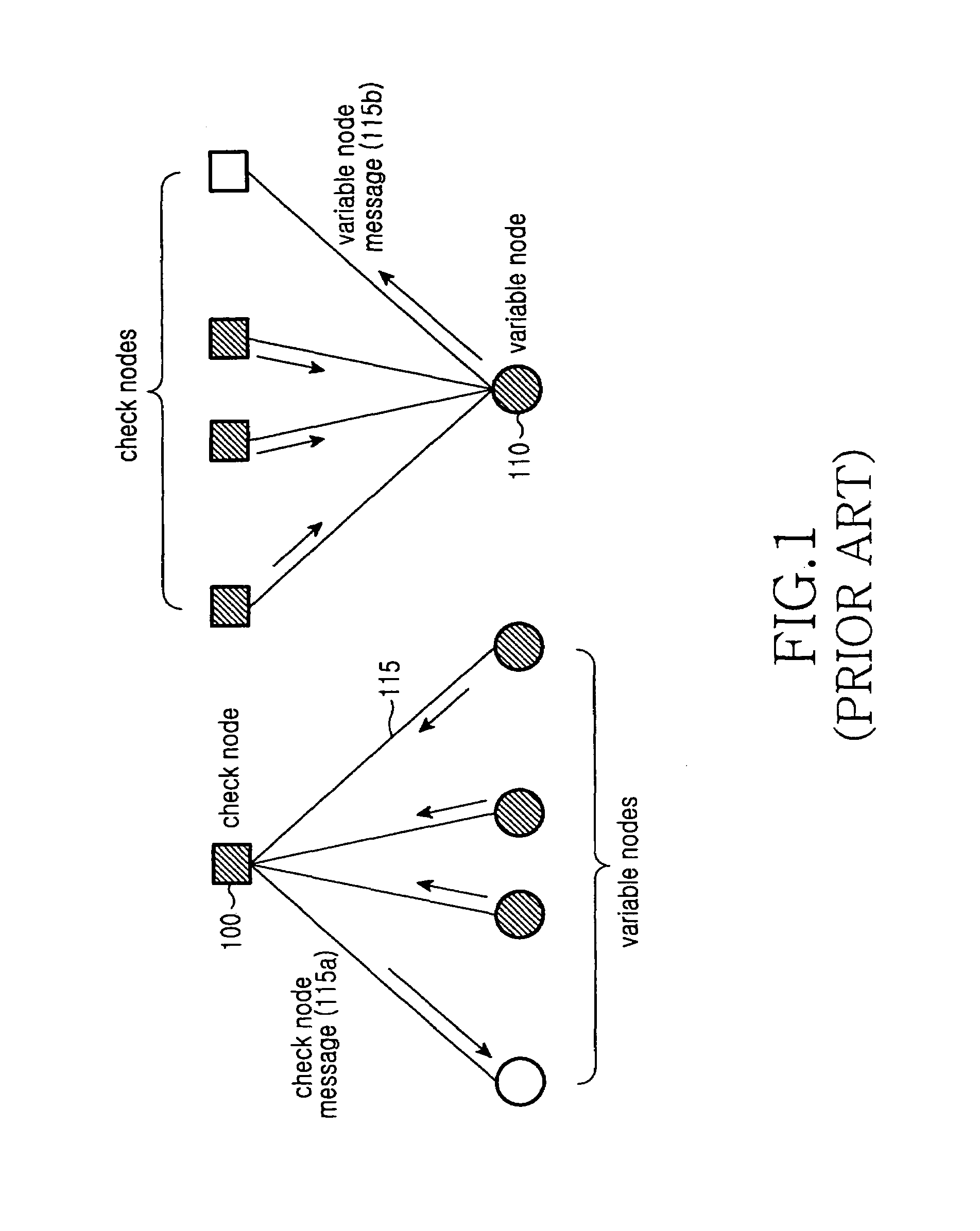
As can be noted from Equation (2) and Equation (3), the variable node message update and the LLR update can be implemented simply with the summation, but the check node message update is expressed in a non-linear function, causing an increase in hardware complexity.
That is, the algorithm must read various types of data from the single memory block to perform corresponding processing, causing a memory access delay.

Method used


Image

  • Method and apparatus for decoding low density parity check code using united node processing
  • Method and apparatus for decoding low density parity check code using united node processing
  • Method and apparatus for decoding low density parity check code using united node processing

Examples


Embodiment Construction

[0054]Exemplary embodiments of the present invention will now be described in detail with reference to the annexed drawings. In the drawings, the same or similar elements are denoted by the same reference numerals even though they are depicted in different drawings. In the following description, a detailed description of known functions and configurations incorporated herein has been omitted for clarity and conciseness.

[0055]FIG. 4 is a diagram illustrating memory segmentation according to a general decoding process.

[0056]Referring to FIG. 4, a memory is provided for a parity check matrix and an identity matrix, respectively. The memories are each segmented into as many sub-metric blocks as the number of nodes, such as check node processors and variable node processors. That is, the rows of the memories are connected in parallel to check nodes, and sub-metric blocks segmented from the columns of the memories are connected in parallel to variable nodes. Each of the small shaded block...


PUM


Abstract

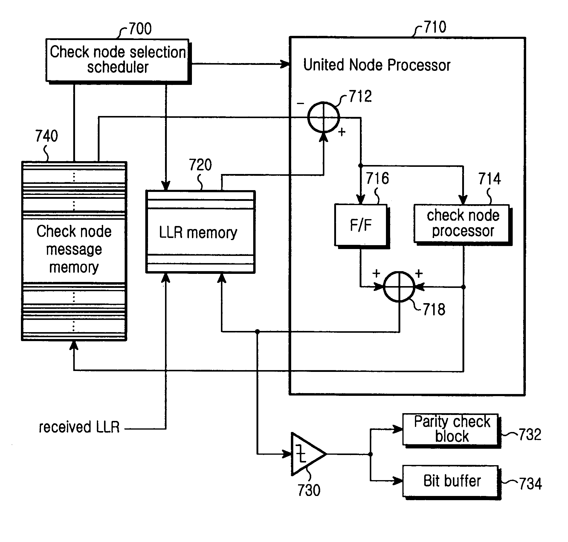
A method and apparatus are provided for decoding an LDPC code including a plurality of check nodes and a plurality of variable nodes. The apparatus includes a check node selection scheduler that selects at least one of the check nodes, an LLR memory that stores an input LLR value for the variable nodes as an initial LLR value and stores updated LLR values for variable nodes connected to the selected check node, and a check node message memory that stores a check node message indicating a result value of check node processing on the selected check node. The apparatus further includes at least one united node processor that generates a variable node message by subtracting the check node message of the selected check node from corresponding LLR values read from the LLR memory, performs check node processing on the variable node message, calculates an LLR value updated by adding the variable node message to the check node processing result value, and delivers the calculated LLR value to the LLR memory.

Description

CROSS-REFERENCE TO RELATED APPLICATIONS[0001]This application claims the benefit under 35 U.S.C. §119(a) of Korean Patent Application No. 10-2004-0096344 entitled “Method And Apparatus For Decoding Low Density Parity Check Code Using United Node Processing” filed in the Korean Intellectual Property Office on Nov. 23, 2004, the entire disclosure of which is incorporated herein by reference.BACKGROUND OF THE INVENTION[0002]1. Field of the Invention[0003]The present invention relates generally to an error correction decoding apparatus and method. More particularly, the present invention relates to a decoding apparatus and method for improving decoding performance by reducing decoding complexity of a Low Density Parity Check (LDPC) code.[0004]2. Description of the Related Art[0005]In general, a digital communication system suffers from errors due to noise generated in a transmission path and corrects the errors with various algorithms to remove the generated errors. In a wireless commun...

Claims


Application Information

Patent Timeline
Patent Type & Authority Patents(United States)
IPC IPC(8): H03M13/00
CPCH03M13/1114H03M13/114H03M13/1137H03M13/116H03M13/11
Inventor KIM, SANG-HYOPARK, SUNG-JINKIM, HAN-JUKIM, MIN-GOO
Owner SAMSUNG ELECTRONICS CO LTD
Learn More