Heat exchanger leak detection using mass gas flow metering

a technology of mass gas flow and heat exchanger, which is applied in the field of heat exchangers, can solve the problems of fluid transfer, undesirable and often dangerous leakage, and leakage between the product chamber and the media chamber

Active Publication Date: 2008-11-25
LOPRESTI WILLIAM J
View PDF24 Cites 23 Cited by
  • Summary
  • Abstract
  • Description
  • Claims
  • Application Information

AI Technical Summary

Benefits of technology

[0012]The present invention is an apparatus and method for detecting leaks in a heat exchanger using mass gas flow metering. Precise mass flow metering equipment is used to detect a separation breakdown between a product chamber and a media chamber in any type of heat exchanger that is used in a heating and / or cooling process. The present method of leak detection has several advantages over the procedures that are currently in use.

Problems solved by technology

Leaks are undesirable and often dangerous.
As the heat exchangers are operated corrosion, erosion, thermal stress and gasket elastomer degradation result in leakage between the product chamber and media chamber.
When leakage occurs during operation, a transfer of fluid from one chamber to the other occurs.
Often leaks become apparent only after the product has leaked into the media, or media into the product.
If the latter occurs, it is likely that the adulterated product will be considered damaged.
In some processes, such as those present in the food, beverage and dairy industries, contamination of this sort may have severe consequences.
Heath risks may occur from contaminated products after the media flows into the product.
This method may work for large leaks, but is not practical for small leak determination.
This method is costly to employ, and is far more complex than a mass flow rate detection method of testing.

Method used


Image

  • Heat exchanger leak detection using mass gas flow metering
  • Heat exchanger leak detection using mass gas flow metering

Examples


Embodiment Construction

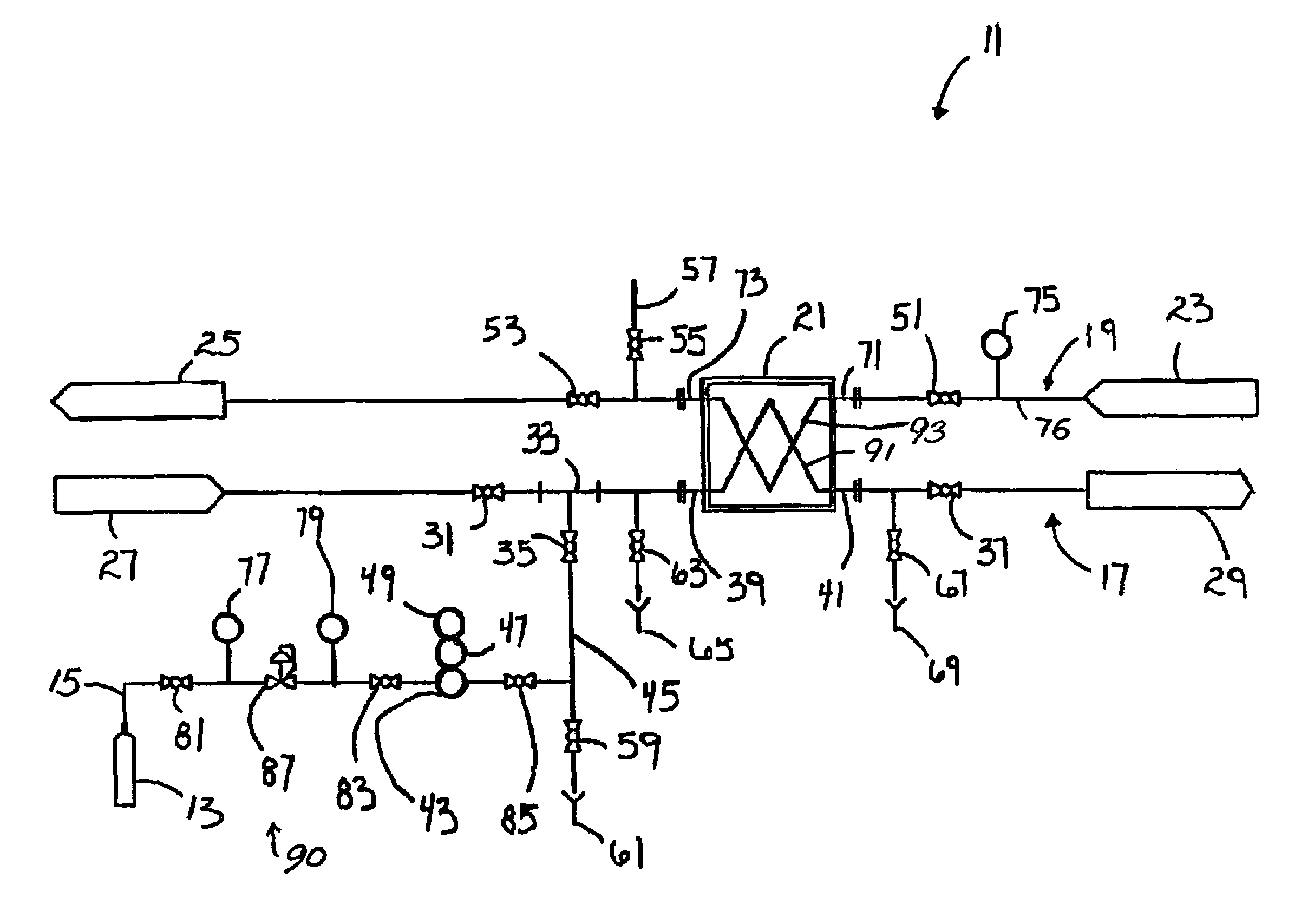
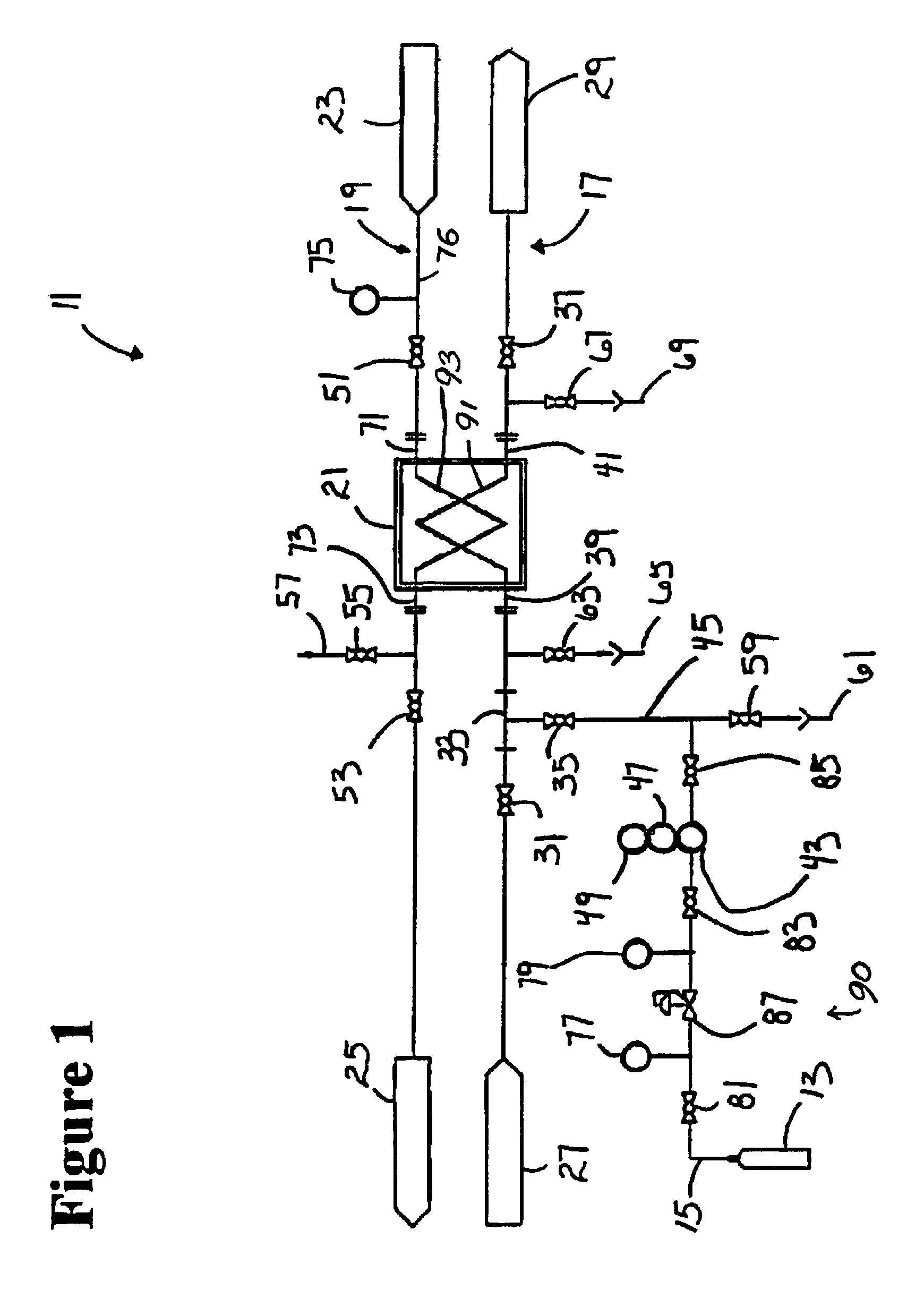
[0019]The present invention provides new testing procedures for leak detection in heat exchangers.

[0020]The flow rate leak test method of the present invention is not designed to completely eliminate the current practice of disassembly and removal of plates for dye checking. The present invention does, however, provide a simple test method that eliminates the need to always disassemble and dye check a heat exchanger to determine if leakage exists. The equipment needed for the flow check test method of the present invention may be made portable for testing multiple units, or installed as a fixed dedicated unit. The flow meter installation may be permanent or temporary. When used as a predictive maintenance tool, this method of testing saves a great deal of unnecessary labor. The disassembling and removing of the plate pack is only necessary if a leak is detected.

[0021]The basic system components and procedures are summarized as follows.

[0022]FIG. 1 is a schematic of the heat exchange...


PUM


Abstract

Apparatus and methods for detecting leaks in a heat exchangers use mass gas flow metering. A regulated gas supply passes through a mass flow meter before entering either the product chamber or media chamber of a heat exchanger. The regulated gas supply passes into the heat exchanger through an inlet connection. All other inlets and outlets to the testing chamber are closed and isolated so that the chamber holds an applied pressure. The chamber on the opposite side of the heat exchanger is opened to atmosphere. Once gas fills the chamber and a static pressure is realized, the test begins by simply monitoring gas flow. If no flow is indicated, no flow rate is detected, and there is no detectable leak. Gas flow into the test chamber, at any given flow rate, as sensed by the sensitive mass flow meter, is an indication that leakage between the chambers exists.

Description

BACKGROUND OF THE INVENTION[0001]A wide variety of heat exchangers exist in the chemical, food, beverage, dairy, and pharmaceutical industries for cooling or heating various liquids. In a typical heat exchanger, heat energy is transferred between two fluids. A barrier separates the two fluids. The barrier may be a gasketed plate, a pipe, or a jacket. The barrier must maintain integrity and separate a product side chamber and a media side chamber. Leaks are undesirable and often dangerous.[0002]Existing heat exchanger designs often employ a tube within a tube design, a tube bundle with multiple tubes attached to a tube sheet that is set in a shell, a spiral tube in a shell, or a design that uses multiple gasketed plates in a frame.[0003]The basic concept of the plate and frame type heat exchanger is to pump fluids on either side of a thin metal plate so that heat may be transferred between the two fluids, e.g. the product and the media.[0004]In all cases the integrity of the barrier ...

Claims


Application Information

Patent Timeline
Patent Type & Authority Patents(United States)
IPC IPC(8): G01M3/22F28D3/02
CPCG01M3/3227G01M3/3254
Inventor LOPRESTI, WILLIAM J.
Owner LOPRESTI WILLIAM J
Why Eureka
Try Eureka