
Device for selectively regulating the flow rate of a fluid

a technology of fluid flow rate and device, which is applied in the direction of engine diaphragms, diaphragm valves, instruments, etc., can solve the problems that the technique does not permit precise metering or control of the flow rate, and achieves simple and reliable use, increasing the versatility of the device

Active Publication Date: 2008-11-25
AVENT INC
View PDF17 Cites 19 Cited by
  • Summary
  • Abstract
  • Description
  • Claims
  • Application Information

AI Technical Summary

Benefits of technology

The device provides precise, stable, and easily changeable flow rates, is economical to manufacture, and simple to use, enhancing versatility and reliability while being suitable for disposable applications.

Problems solved by technology

It is sometimes necessary to control the flow rate at which the liquid is delivered to the patient, particularly when the liquid is to be administered continuously over an extended period of time.
The technique does not, however, permit precise metering or control of the flow rate.

Method used


Image

  • Device for selectively regulating the flow rate of a fluid
  • Device for selectively regulating the flow rate of a fluid
  • Device for selectively regulating the flow rate of a fluid

Examples


Embodiment Construction

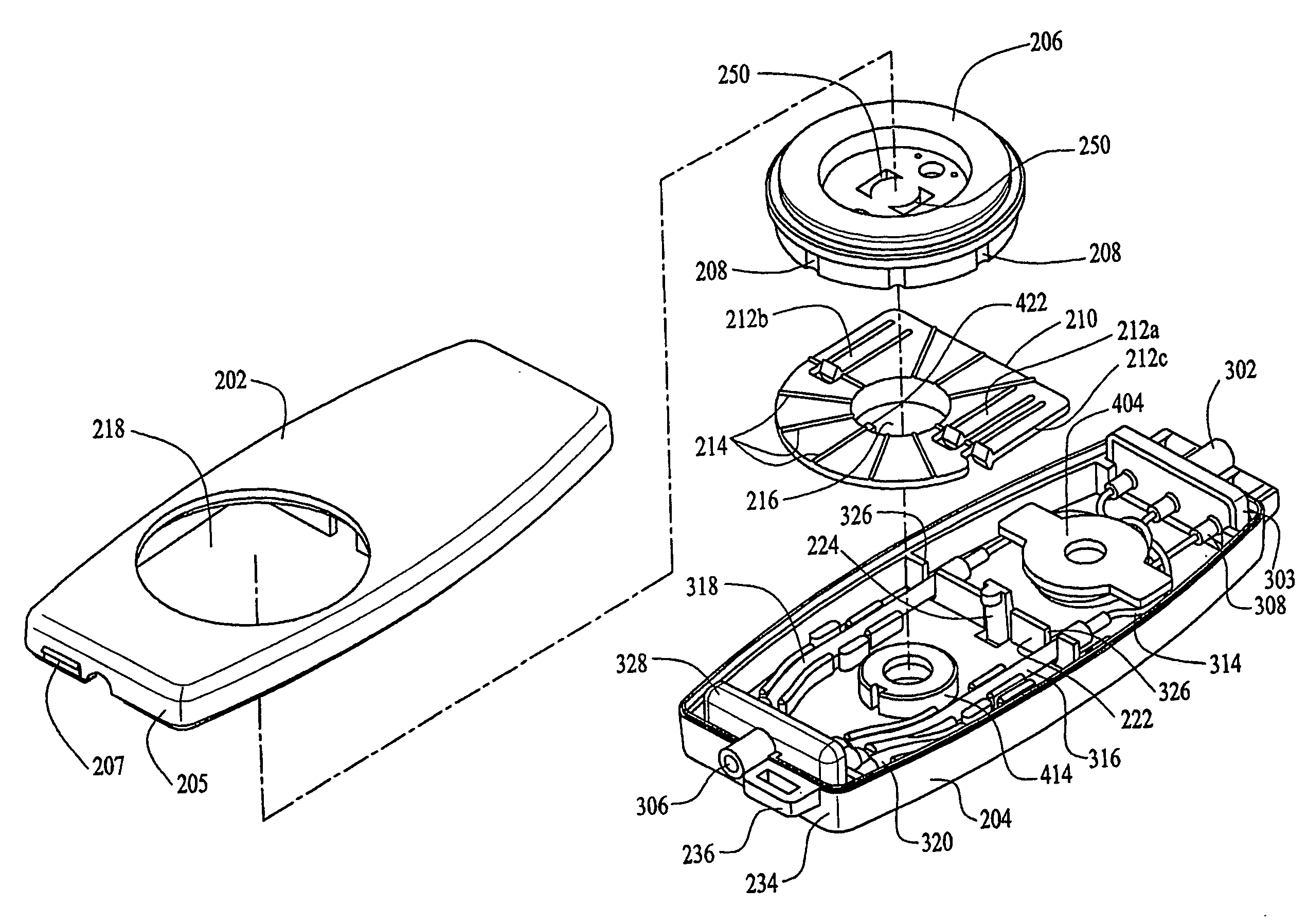
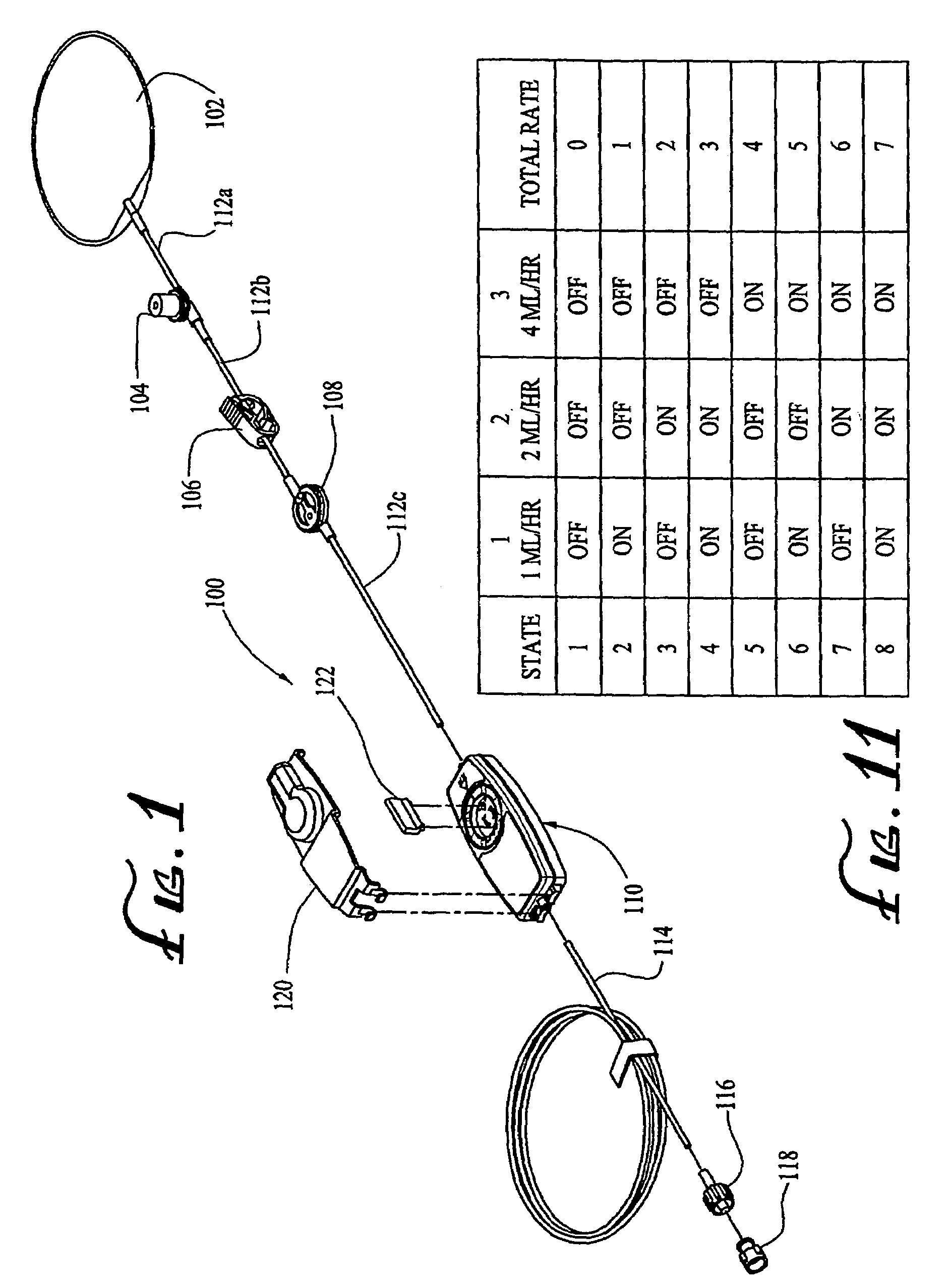
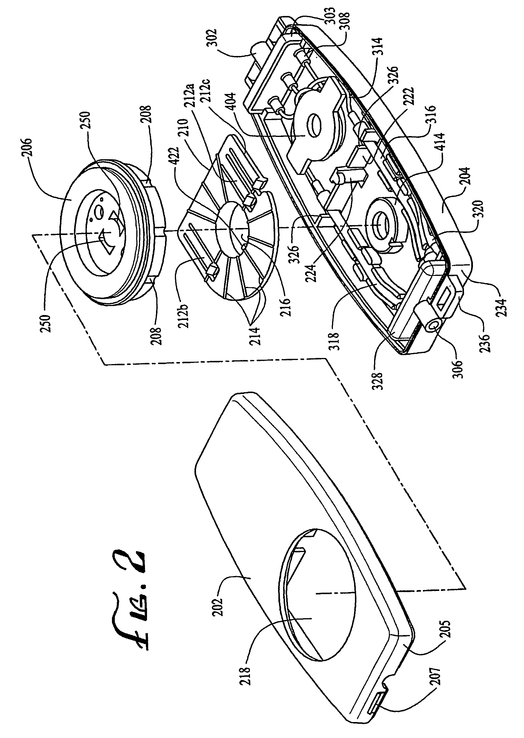
[0021]Referring to FIG. 1, an infusion system 100 is shown, in which a flow rate regulating device 110 in accordance with the present invention may be employed. The infusion system 100 includes a fluid reservoir 102, which may be a bag as shown. The reservoir bag 102 is typically pre-filled with a volume of a therapeutic liquid (e.g., a medicinal agent), and is of a known type that is advantageously pressurized by a pump (not shown) that controllably applies a positive pressure to the reservoir bag 102. The reservoir bag 102 is fluidly connected to the inlet of the regulating device 110 by an upstream IV line 112, which comprises several segments of flexible tubing cut to suitable lengths. A first segment 112a connects the outlet of the reservoir bag 102 with the inlet of a conventional fill valve 104. The fill valve 104 allows additional doses of a therapeutic agent (which may be something other than that with which the reservoir bag 102 is filled) to be administered as needed to t...


PUM


Abstract

A device for regulating the flow rate of a fluid includes a housing containing a plurality of flow conduits fluidly connecting an inlet and an outlet, each of the flow conduits comprising a flow control tube (310, 312, 314) and a resiliently compressive occlusion tube (316, 318, 320), wherein the flow control tubes are of substantially equal internal diameter. Each of the flow control tubes has a length associated with a different flow rate. A resilient flow-blocking element (212a, 212b, 212c) is operatively associated with each of the occlusion tubes and is movable into a flow-blocking compression against its associated occlusion tube. An actuation mechanism (206) in the housing is operable: (a) to selectively engage and move one or more of the flow-blocking elements into the flow-blocking compression against its associated occlusion tube, and (b) to selectively be disengaged from any of the flow-blocking elements.

Description

CROSS REFERENCE TO RELATED APPLICATION[0001]This application claims the benefit, under 35 U.S.C. Section 119(e), of co-pending U.S. provisional application No. 60 / 412,409, filed 19 Sep. 2002, the disclosure of which is incorporated herein by reference.FEDERALLY SPONSORED RESEARCH OR DEVELOPMENT[0002]Not ApplicableBACKGROUND OF THE INVENTION[0003]The present invention relates generally to devices for regulating the flow of intravenous fluids. More specifically, it relates to devices that permit the selection of any of a plurality of discrete flow rates for the continuous infusion of intravenous liquids.[0004]In the medical field, therapeutic or medicinal liquids are often administered to a patient by intravenous (IV) infusion system. In an infusion system, the liquid is typically contained in a reservoir (a bag or a bottle) suspended above the patient, and delivered through a tube, by the force of gravity, to an IV needle inserted into the patient's vasculature. Alternatively, the li...

Claims


Application Information

Patent Timeline
Patent Type & Authority Patents(United States)
IPC IPC(8): A61M39/28F16K7/06A61M5/168A61M5/14
CPCA61M5/16877A61M39/28A61M5/14A61M5/141A61M39/285Y10T137/86558Y10T137/87161Y10T137/87306A61M5/168
Inventor MABRY, ERICRAKE, KENNETH WAYNE
Owner AVENT INC
Learn More