Fuel injector with direct-controlled injection valve member

a technology of direct control and fuel injector, which is applied in the direction of fuel injection apparatus, engine components, feed systems, etc., can solve the problems of increasing the installation space in the region and the cooling of the cylinder head region is more complicated for internal combustion engines with high specific power per liter displacement, so as to shorten the current supply time of the piezoelectric actuator

Inactive Publication Date: 2008-11-25
ROBERT BOSCH GMBH
View PDF8 Cites 29 Cited by
  • Summary
  • Abstract
  • Description
  • Claims
  • Application Information

AI Technical Summary

Benefits of technology

[0005]Fuel injectors for reservoir injection systems are as a rule triggered via solenoid valves or piezoelectric actuators. By means of the solenoid valves or piezoelectric actuators, a pressure relief of a control chamber is effected. To that end, the control chamber has a relief conduit, in which as a rule there is an outlet throttle. Filling the control chamber for actuating the injection valve member is as a rule done via an inlet from valve associated with the control chamber, or the piezoelectric actuator associated with it, a valve closing member is actuated, which closes the outflow conduit. Upon actuation of the solenoid valve or piezoelectric actuator, the valve closing member, which may for example be a ball body or a cone, uncovers the outflow conduit, so that a control volume is capable of flowing out of the control chamber. As a result, the pressure in the control chamber drops, and an injection valve member, as a rule embodied as a needle, acted upon by the control chamber moves vertically upward. As a result of the upward motion of the injection valve member, injection openings on the end of the fuel injector toward the combustion chamber are uncovered, so that fuel can be injected into the combustion chamber of an internal combustion engine.
[0006]The fuel injectors known from the prior art, which are actuatable via solenoid valves or piezoelectric actuators, as a rule include an injector body, which is constructed in pressureproof and pressuretight fashion. The solenoid valve or piezoelectric actuator is received outside this injector body. As a result, the pressure level in the control chamber is lowered via the opening of the outflow conduit. On this principle, an actuation of the needle-like injection valve member is effected indirectly. A hydraulic booster device is as a rule associated with the piezoelectric actuator that is located outside the valve body, so that the stroke travel of the piezoelectric actuator can be lengthened, since the piezoelectric crystals, in stacked form, when supplied with current have only a slight change in length. If conversely the fuel injector is actuated via a solenoid valve, then it is necessary that its remnant air gap and armature stroke travel be adjusted exactly, in order to trigger the valve closing member, which closes the outflow conduit of the control chamber, suitably precisely, particularly in the high rpm range of an internal combustion engine.

Problems solved by technology

The trend in modem engines, however, is to increasingly less available installation space in the region of the cylinder head.
This is associated with the fact that internal combustion engines with high specific power per liter of displacement require more-complicated cooling of the cylinder head region.

Method used


Image

  • Fuel injector with direct-controlled injection valve member
  • Fuel injector with direct-controlled injection valve member

Examples


Embodiment Construction

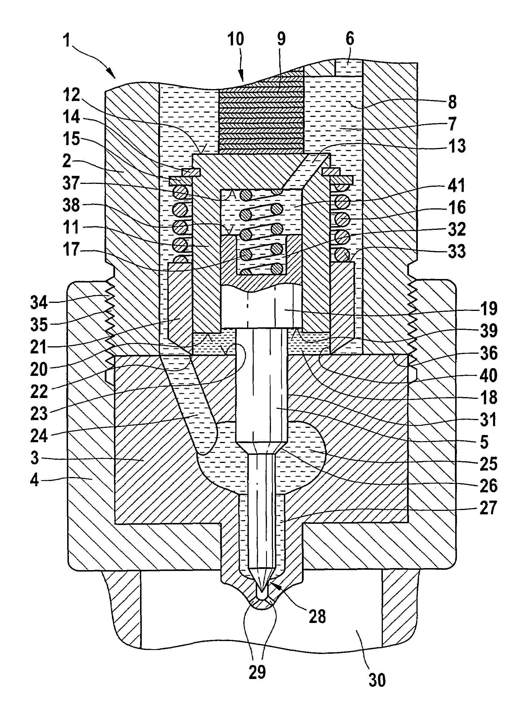
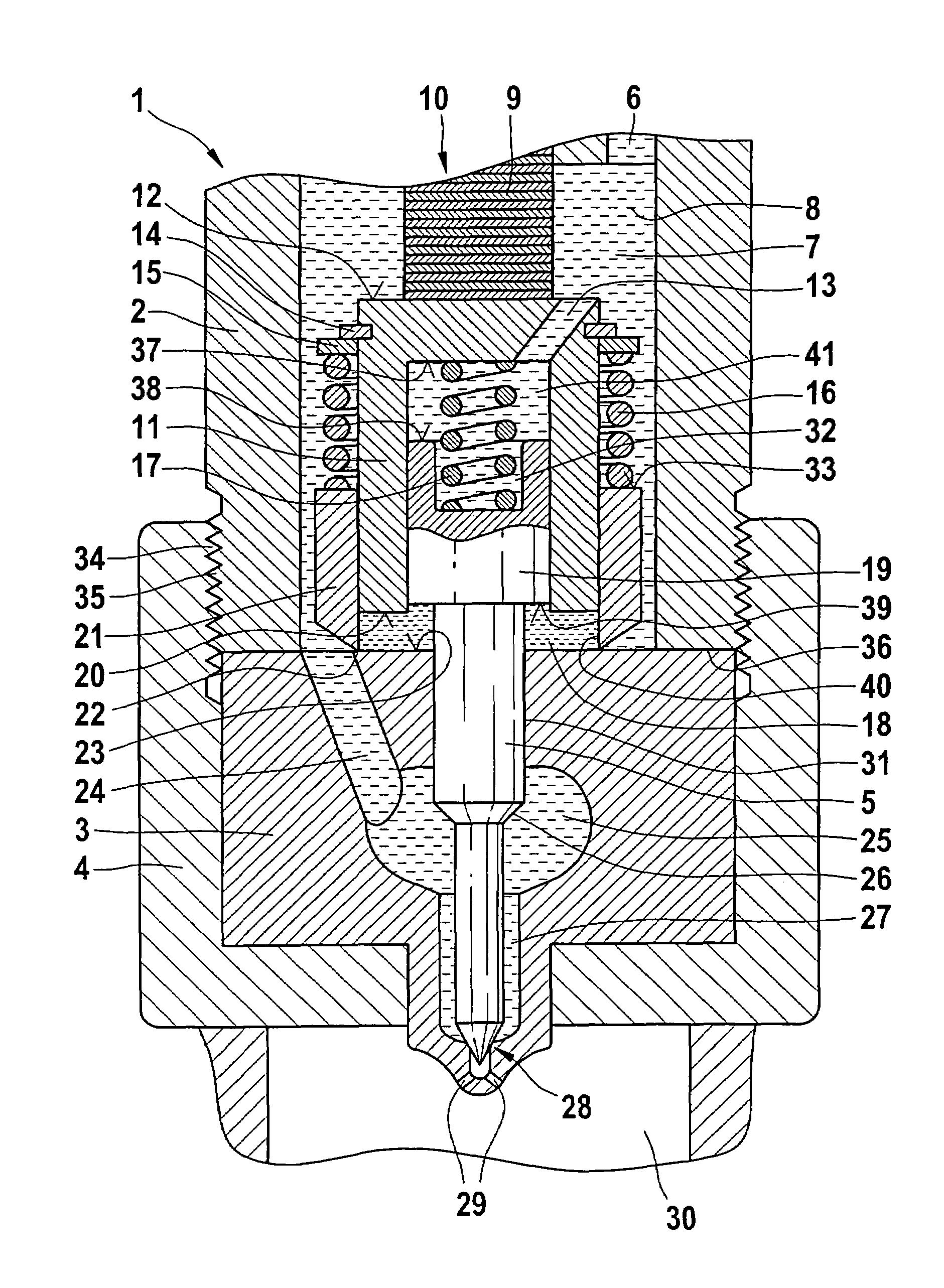
[0012]The drawing shows a fuel injector 1, which includes an injector body 2 connected to a nozzle holder 3 via a nozzle lock nut 4. This arrangement is also known as a nozzle holder combination. For connecting the injector body 2 and the nozzle holder 3, a male-threaded portion 34 is provided on the injector body, onto which the nozzle lock nut 4, provided with a female thread 35, is tightened at a predetermined torque. The nozzle lock nut 4 surrounds the nozzle holder 3 with an annular contact face.

[0013]In the injector body 2, a high-pressure inlet 6 is provided, which communicates with a high-pressure storage volume (common rail), not shown in the drawing. The high-pressure storage volume is acted upon via a high-pressure pump, not shown in the drawing. The pressure level (system pressure) that prevails in the common rail is in the range between 1400 bar and 1600 bar. Via the high-pressure inlet 6, a pressure chamber 7, which is embodied in the injector body 2, is subjected to f...


PUM


Abstract

A fuel injector for injecting fuel into a combustion chamber of an internal combustion engine, the injector having body and a nozzle holder in which an injection valve member is movably received, which injection valve member has a seat that opens or closes injection openings, and the injection valve member is actuatable via a piezoelectric actuator. The piezoelectric actuator actuates a first booster piston, in which a second booster piston, connected to the injection valve member is guided.

Description

CROSS-REFERENCE TO RELATED APPLICATIONS[0001]This application is a 35 USC 371 application of PCT / EP 2004 / 053230 filed on Dec. 2, 2004.BACKGROUND OF THE INVENTION[0002]1. Field of the Invention[0003]In internal combustion engines, reservoir injection systems (common rail systems) are increasingly used today; they make it possible to adjust the injection pressure independently of rpm and load. In common rail systems, the pressure generation and the injection event are decoupled from one another both chronologically and in terms of location. The injection pressure is generated by a separate high-pressure pump. This pump need not necessarily be driven synchronously with the injections. The pressure can be adjusted independently of the engine rpm and the injection quantity. In common rail systems, instead of pressure-controlled injection valves, electrically actuated injectors are used, with which the triggering instant and duration of triggering, the injection onset, and the injection q...

Claims


Application Information

Patent Timeline
Patent Type & Authority Patents(United States)
IPC IPC(8): B05B1/08F02M51/06F02M57/02F02M63/00
CPCF02M51/0603F02M2200/703F02M2200/704
Inventor BOECKING, FRIEDRICH
Owner ROBERT BOSCH GMBH
Why Eureka
Try Eureka