Surface light source device

a light source device and surface technology, applied in lighting devices, lighting and heating devices, instruments, etc., can solve problems such as pressure drop, and achieve the effect of reducing the pressure drop

Inactive Publication Date: 2008-11-25
ORMON CORP
View PDF7 Cites 6 Cited by
  • Summary
  • Abstract
  • Description
  • Claims
  • Application Information

AI Technical Summary

Benefits of technology

[0011]Embodiments of the present invention provide a surface light source device which is capable of suppressing generation of such aforementioned bright line and is difficult to generate crush of pattern of the backside of a light guide plate even when pressure is applied.

Problems solved by technology

However, in the method in which the projection 22 of the triangle prism shape is projected on the backside of the light guide plate 14, there arises a problem in that when pressure is applied from the reflecting plate 16 side of the backside of the light guide plate 14, the projection 22 is crashed due to the pressure.

Method used


Image

  • Surface light source device
  • Surface light source device
  • Surface light source device

Examples


first embodiment

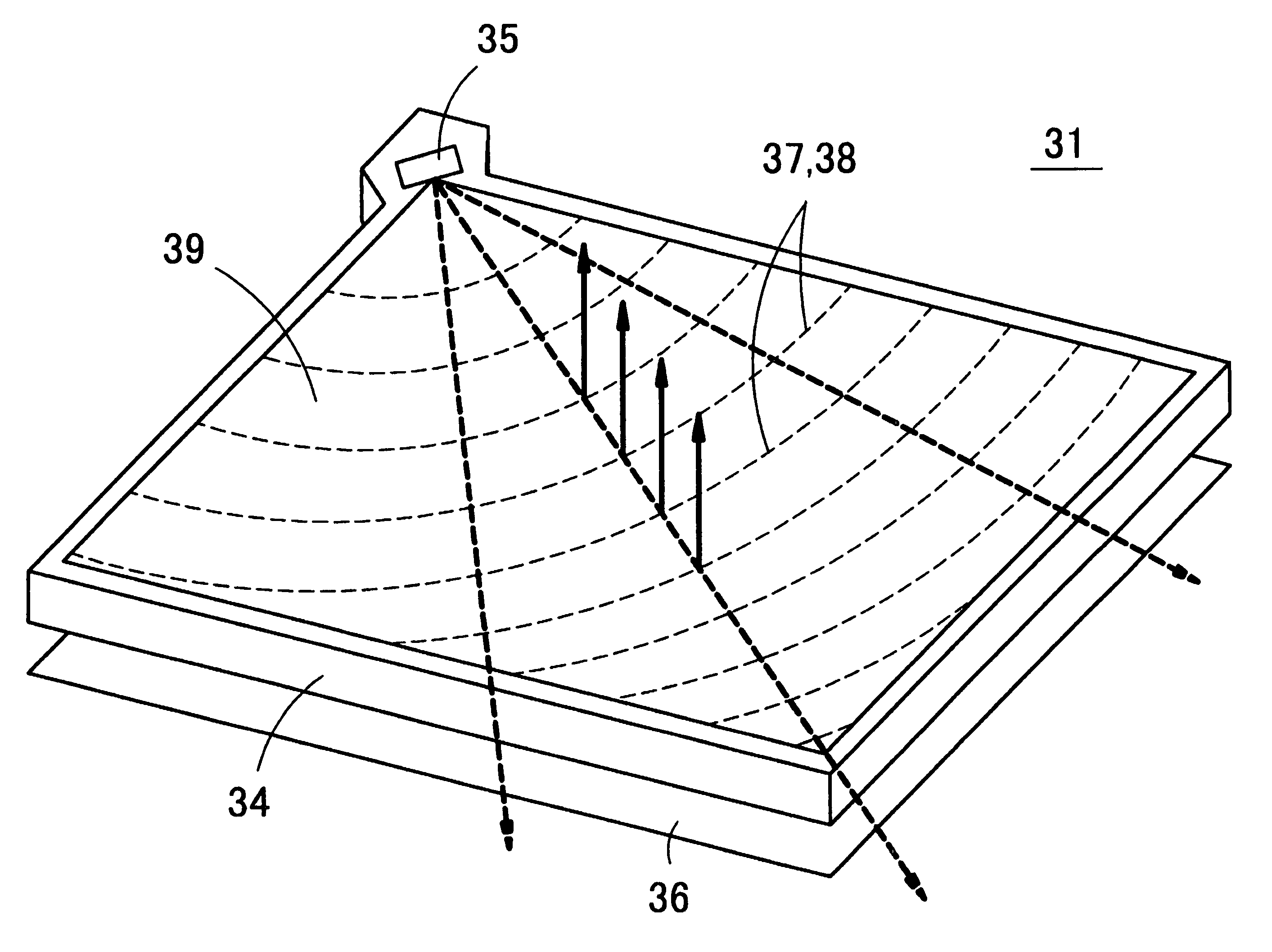
[0060]FIG. 5 shows a perspective view of a surface light source device according to the present invention. As shown in FIG. 5, a surface light source device 31 is one in which a small light source 35 is arranged at a corner portion of a light guide plate 34 made of a transparent resin material and a reflecting plate 36 is arranged facing the backside of the light guide plate 34. The light guide plate 34 is molded by a transparent resin material, such as polycarbonate resin, polymethylmethacrylate, and cyclo olefin polymer (referred to as COP). A number of fine deflection patterns 37 and fine diffusion patterns 38 are formed on the backside of the light guide plate 34 arrayed in concentric circles with a central focus on the position of the light source 35. The deflection patterns 37 and the diffusion patterns 38 are arranged with relatively low density in the vicinity of the light source 35 and arranged with gradually high density with being apart from the light source 35 so that th...

second embodiment

[0086]FIG. 17 shows a schematic perspective view of a deflection pattern 37 and a diffusion pattern 38 provided on the backside of a light guide plate in a surface light source device according to a Furthermore, FIG. 18 shows a view of a cross section of the diffusion pattern 38 and a sectional view taken along the line X4-X4 shown in FIG. 17.

[0087]In the second embodiment, one incorporating a tricolor LED with red green and blue colors, is used as a light source 35. Then, red light, green light, and blue light are mixed to generate white light.

[0088]Furthermore, in the second embodiment, a diffusion pattern 38 is of a substantially sine wave shape in cross section; however, horizontal distance between sine wave shaped adjacent projections (pitch P of the diffusion pattern 38) is not constant but changes in a random manner. The minimum value Pmin of the pitch P of the diffusion pattern 38 is not less than 1.5 μm and the maximum value Pmax of the pitch P of the diffusion pattern 38 ...

fifth embodiment

[0103]FIG. 30 shows a perspective view of a liquid crystal display 61 provided with a surface light source device 32 according to the present invention. FIG. 31 shows a schematic sectional view of the aforementioned liquid crystal display 61. That is, a liquid crystal panel 33 is arranged in front of the surface light source device 32. In such the liquid crystal display 61, the liquid crystal panel 33 can be vertically illuminated from the backside by the surface light source device 32 without using a prism panel or the like. Then, the bright line is not generated in the liquid crystal display 61 and image visibility is improved by using the surface light source device 32 according to the present invention. In addition, there is not a possibility to damage the diffusion pattern 38 by external force and shock.

[0104]In addition, a diffusion plate 63 may be sandwiched between the surface light source device 32 and the liquid crystal panel 33 as shown in FIG. 32, if needed.

[0105]Further...


PUM


Abstract

A surface light source device capable of suppressing generation of bright line and preventing generation of crush of pattern forming on a light guide plate even when pressure is applied, includes a plurality of deflection patterns and diffusion patterns wherein the diffusion pattern is formed on the light source side of the deflection pattern. Further, the diffusion pattern is provided so as not to protrude outwards from the light guide plate from the plane opposite to the light-emitting plane and the diffusion pattern diffuses the light incident from a light guide direction to a direction different from the light guide direction seen from a direction perpendicular to the light emitting plane.

Description

BACKGROUND OF THE RELATED ART[0001]1. Field of the Invention[0002]The present invention relates to a surface light source device and, more particularly, to a surface light source device used as a back light, a front light, and a reversible light, for use in a liquid crystal display.[0003]2. Description of the Related Art(Prior Art 1)[0004]FIG. 1A shows a schematic sectional view of a structure of a conventional liquid crystal display (see Japanese Patent Gazette No. 3151830) and FIG. 1B shows an enlarged view of a part of FIG. 1A. FIG. 2 shows a schematic perspective view of a back light used in the aforementioned liquid crystal display.[0005]A liquid crystal display 11 is constituted by overlapping a liquid crystal panel 13 on the surface side of a back light 12. The back light 12 is one in which a small light source 15 is arranged at a corner portion of a light guide plate 14 and a reflecting plate 16 is arranged facing the backside of the light guide plate 14. Deflection patterns...

Claims


Application Information

Patent Timeline
Patent Type & Authority Patents(United States)
IPC IPC(8): F21V7/04
CPCG02B6/0038G02F2201/34G02F2203/03G02F1/1335
Inventor SAKURAI, KENJIOHHIRA, MAKOTOKURATA, GOUOKAWABATA, YASUHIROSHINOHARA, MASAYUKI
Owner ORMON CORP
Why Eureka
Try Eureka