Cyclotron equipped with novel particle beam deflecting means

a cyclotron and beam deflector technology, applied in the direction of masers, electric discharge tubes, laser details, etc., can solve the problems of difficult acceleration of such negative particles, fragile negative ions, and limited space within the cyclotron itsel

Inactive Publication Date: 2008-11-25
ION BEAM APPL
View PDF8 Cites 106 Cited by
  • Summary
  • Abstract
  • Description
  • Claims
  • Application Information

AI Technical Summary

Problems solved by technology

Nevertheless, the acceleration of such negative particles poses considerable difficulties.
The main disadvantage stems from the fact that the negative ions are fragile and so are easily dissociated by residual gas molecules or by considerable magnetic fields crossed with high energy and present in the cyclotron.
Another reason for which the injection devices and the source are located on the outside of the cyclotron is that the space available within the cyclotron itself is very limited.
The presence of an inflector of this type intended to allow the introduction of the particle beam through the central (vertical) axis generates the presence of a hole in the air-gap and therefore disturbs the vertical magnetic field.
The other disadvantages stem from the fact that these electrodes must be subjected to a potential difference which is all the more important as the intensity of the particle beam is important.
Another significant problem stems from the fact that, in order to increase the intensity of the particle beam, the space charge is increased, i.e. the density of the electric charge, thus bringing about the electrostatic repulsion of the charges, and so a broadening of the beam (electric charges brought about by the presence of numerous charged particles which mutually repel one another within a space, thus causing an increase in the beam size).
This, of course, would be the cause of a whole series of problems inherent to electrodes, like in particular problems of insufficient insulation or breakdown of the said electrodes.
A final problem stems from the rotational symmetry of the isochronous cyclotron which comprises alternating hills and valleys.
For this type of cyclotron, the focusing takes place by staggered gradients and is particularly delicate at the centre of the cyclotron because the modulation effect of the field due to the hills and valleys disappears at the centre of the cyclotron.
This device is only applicable to separate sector cyclotrons because the deflection electromagnets require space which is not available in the central section of a compact cyclotron.

Method used


Image

  • Cyclotron equipped with novel particle beam deflecting means
  • Cyclotron equipped with novel particle beam deflecting means
  • Cyclotron equipped with novel particle beam deflecting means

Examples


first embodiment

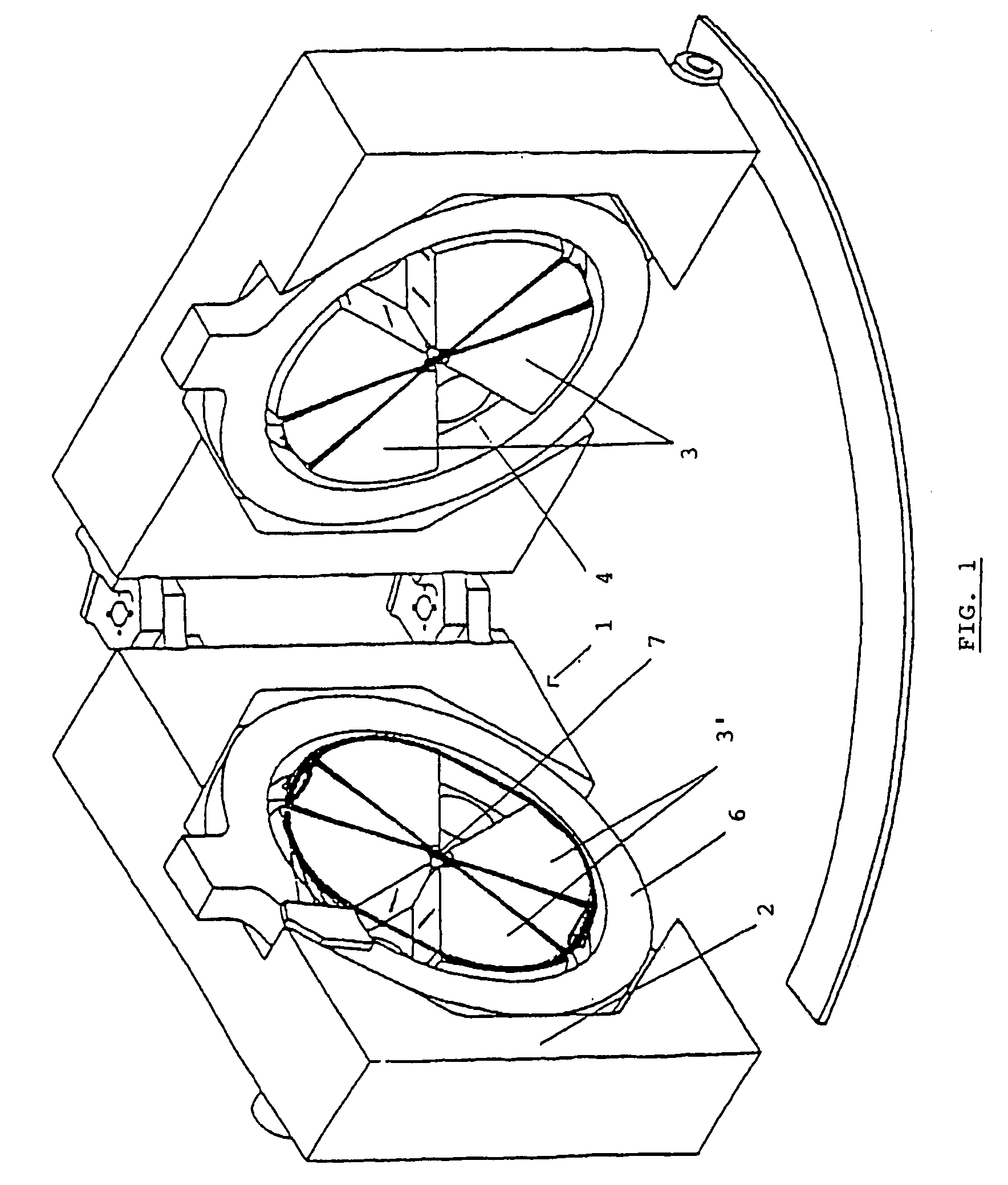
[0060] described under FIGS. 3a and 3b, this type of inflector is made up of parts which form the magnetic circuit in the central zone of the cyclotron. These parts are integral with the poles and are made from a ferro-magnetic material which makes it possible to introduce a horizontal or radial component to the magnetic field.

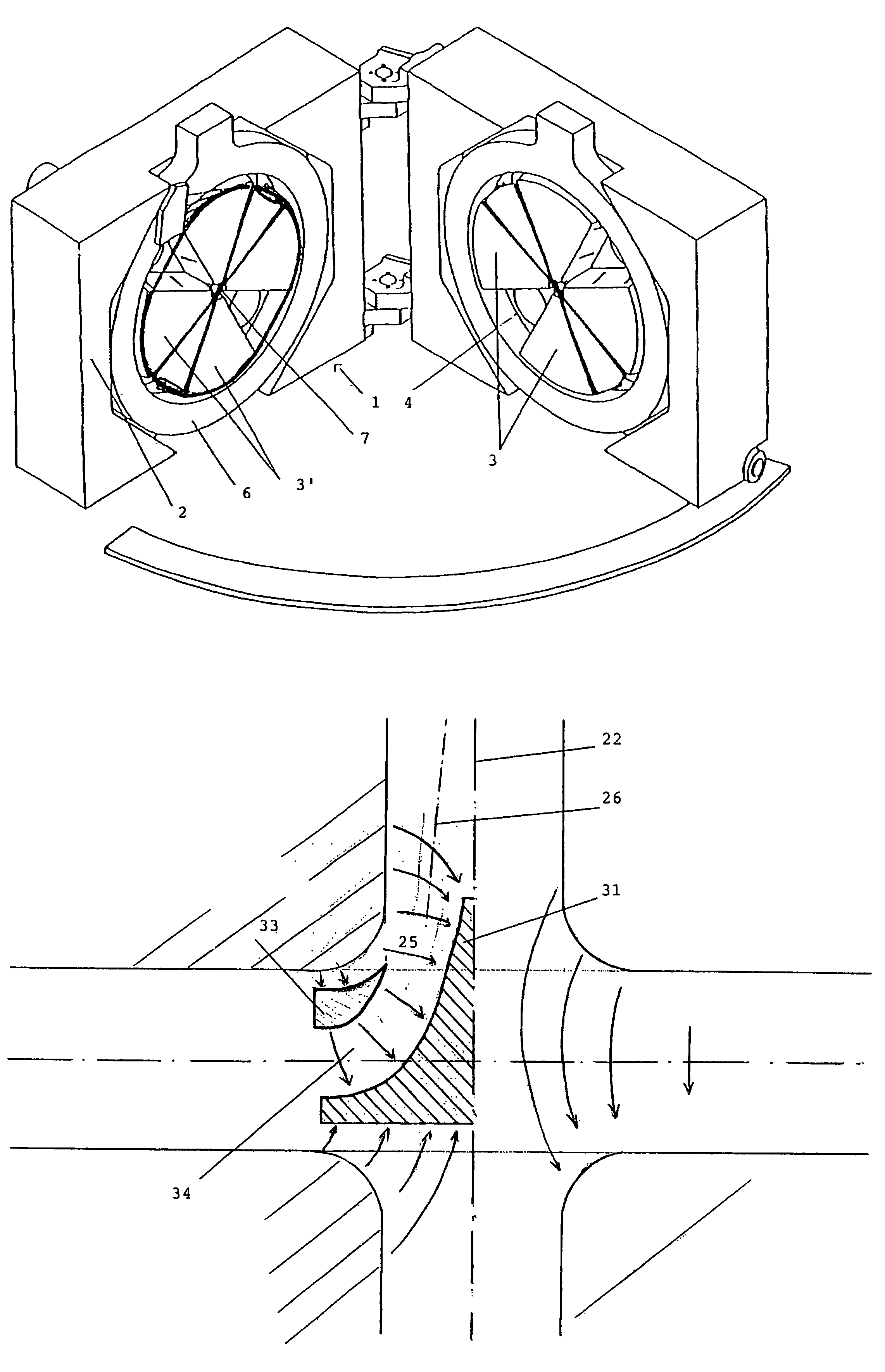
[0061]According to a variation of this preferred embodiment, the inflection means are made up of a first element 31 in the form of a cone and of which the axis of symmetry coincides with the axis 22 of the cyclotron and a second element 33 which is essentially in the form of a ring, with the same axis of symmetry, and which essentially surrounds the cone 31, in such a way as to form an annular space 34 between the two elements 31 and 33. These elements are necessarily made from a ferro-magnetic material, such as a steel with a low level of carbon or an iron-cobalt alloy.

[0062]The positioning of these will create a disturbance of the magnetic field 25 between t...

second embodiment

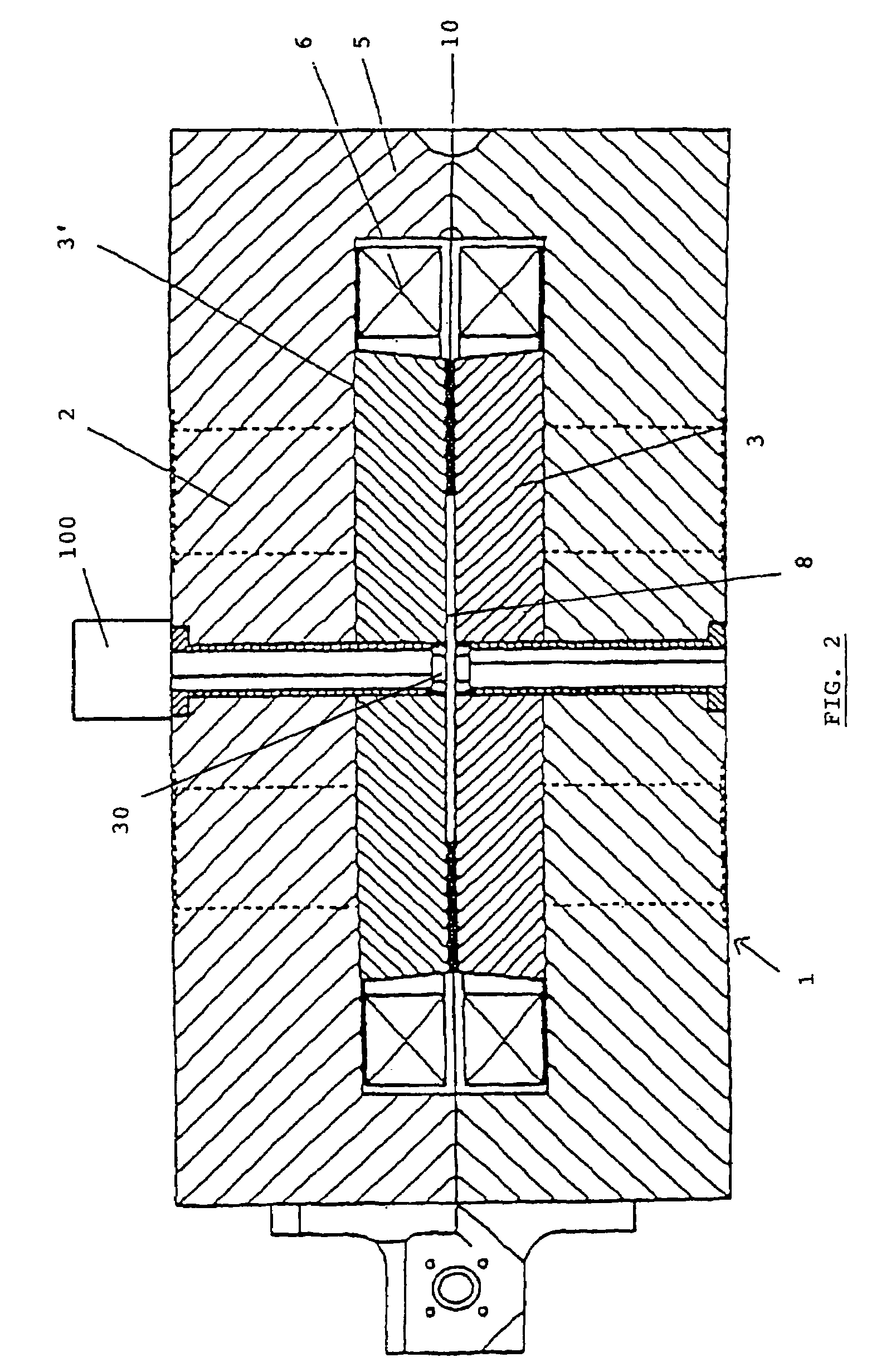
[0069]The solution, as represented by FIGS. 4 and 5, and which corresponds to the second embodiment, makes it possible, by positioning a series of ring-shaped magnets in the centre of the cyclotron, to progressively inflect the beam originating from the axial injector in accordance with a path formed by the central point of successive rings. This path is symbolized by a spiral.

[0070]According to this last embodiment, the solution will have the advantage of not requiring the presence of deflection devices, such as guiding coils, upstream from the inflection elements.

[0071]A practical example makes it possible to contemplate the acceleration of H particles in a cyclotron of 115 MeV for an injection energy of 80 kV. The magnetic field at the centre will be BC=0.811 T with a magnetic rigidity of 4.15 T·cm. The radius from the centre of the cyclotron will be 5.12 cm, and the connection radius will be between 6 and 7 cm.


PUM


Abstract

The invention concerns a cyclotron for accelerating a charged particle beam circulating in the median plane essentially in the form of two poles inducing a magnetic field and having a so-called axial injector, that is an injector arranged outside the cyclotron substantially along the main axis of the cyclotron and hence perpendicular to the median plane thereof and which is combined with deflecting means which enable the particle beam to be deflected until it is positioned in the median plane. The invention is characterized in that the deflecting means consist of a magnetic deflector.

Description

AIM OF THE INVENTION[0001]This invention aims to propose a cyclotron equipped with a novel type of inflector used to “inflect” a charged particle beam injected axially by an injection device or an injector towards the median plane of the cyclotron.PRIOR ART[0002]Cyclotrons are charged particle accelerators used in particular in order to produce radioactive isotopes. These cyclotrons are based on the elementary principles of the force of Lorenz: F=qv×B which induces the fact that a charged particle essentially describes the arc of a circle in a uniform magnetic field perpendicular to the plane in which the charged particle moves.[0003]Cyclotrons are comprised of several distinct main units such as the electromagnet which guides the charged particles, the high frequency resonator which is responsible for the acceleration of the said particles and finally the injection system of the said particles in the cyclotron.[0004]The combination of the different means makes it possible to bring ...

Claims


Application Information

Patent Timeline
Patent Type & Authority Patents(United States)
IPC IPC(8): H05H13/00
CPCH05H7/08H05H13/00
Inventor JONGEN, YVES
Owner ION BEAM APPL
Why Eureka
Try Eureka