Beam-forming antenna with amplitude-controlled antenna elements

a beamforming antenna and antenna element technology, applied in the field of directional antennas, can solve the problems of increasing the weight, size, cost and complexity of the antenna system, gimbal-mounted parabolic reflectors, which are relatively massive and slow, and achieve the effect of less cos

Active Publication Date: 2008-11-25
SIERRA NEVADA CORP
View PDF29 Cites 33 Cited by
  • Summary
  • Abstract
  • Description
  • Claims
  • Application Information

AI Technical Summary

Benefits of technology

[0009]As will be more readily appreciated from the detailed description that follows, the present invention provides an antenna that can transmit and / or receive electromagnetic radiation in a beam having a shape and, in particular, a direction that can be controllably selected and varied. Thus, the present invention provides the beam-shaping control of a phased array antenna, but does so by using amplitude controlling devices that are inherently less costly and more stable than the phase shifters employed in phased array antennas.

Problems solved by technology

This type of antenna requires a motor and a transmission and control mechanism to rotate the drum in a controllable manner, thereby adding to the weight, size, cost and complexity of the antenna system.
Other approaches to the problem of directing electromagnetic radiation in selected directions include gimbal-mounted parabolic reflectors, which are relatively massive and slow, and phased array antennas, which are very expensive, as they require a plurality of individual antenna elements, each equipped with a costly phase shifter.

Method used


Image

  • Beam-forming antenna with amplitude-controlled antenna elements
  • Beam-forming antenna with amplitude-controlled antenna elements
  • Beam-forming antenna with amplitude-controlled antenna elements

Examples


Embodiment Construction

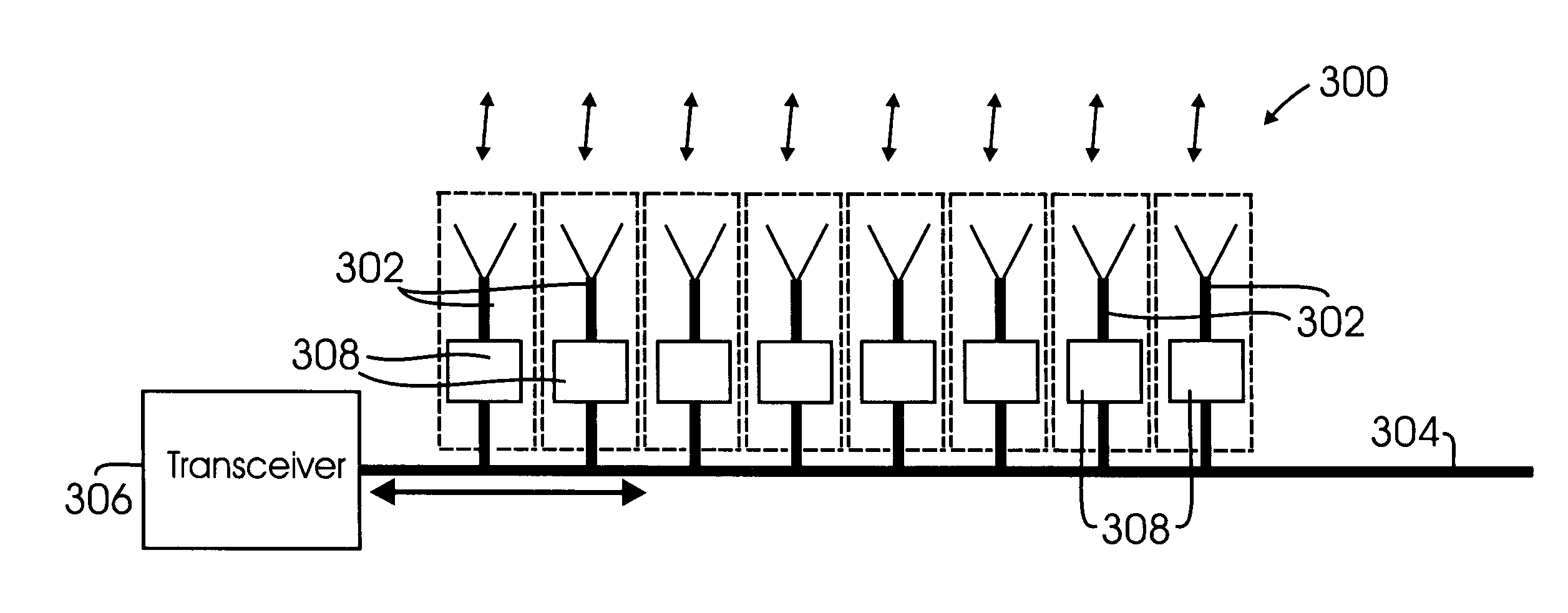
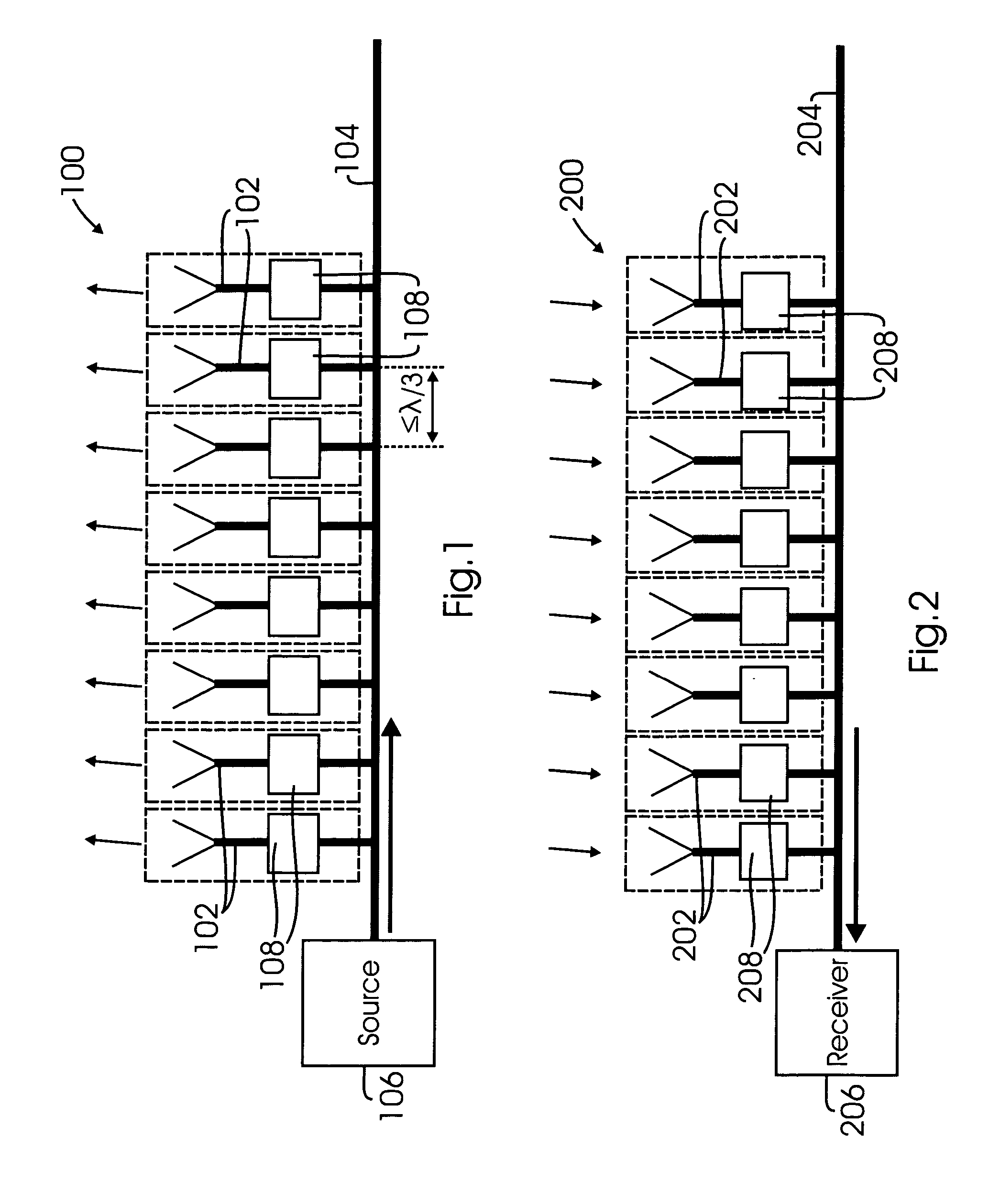
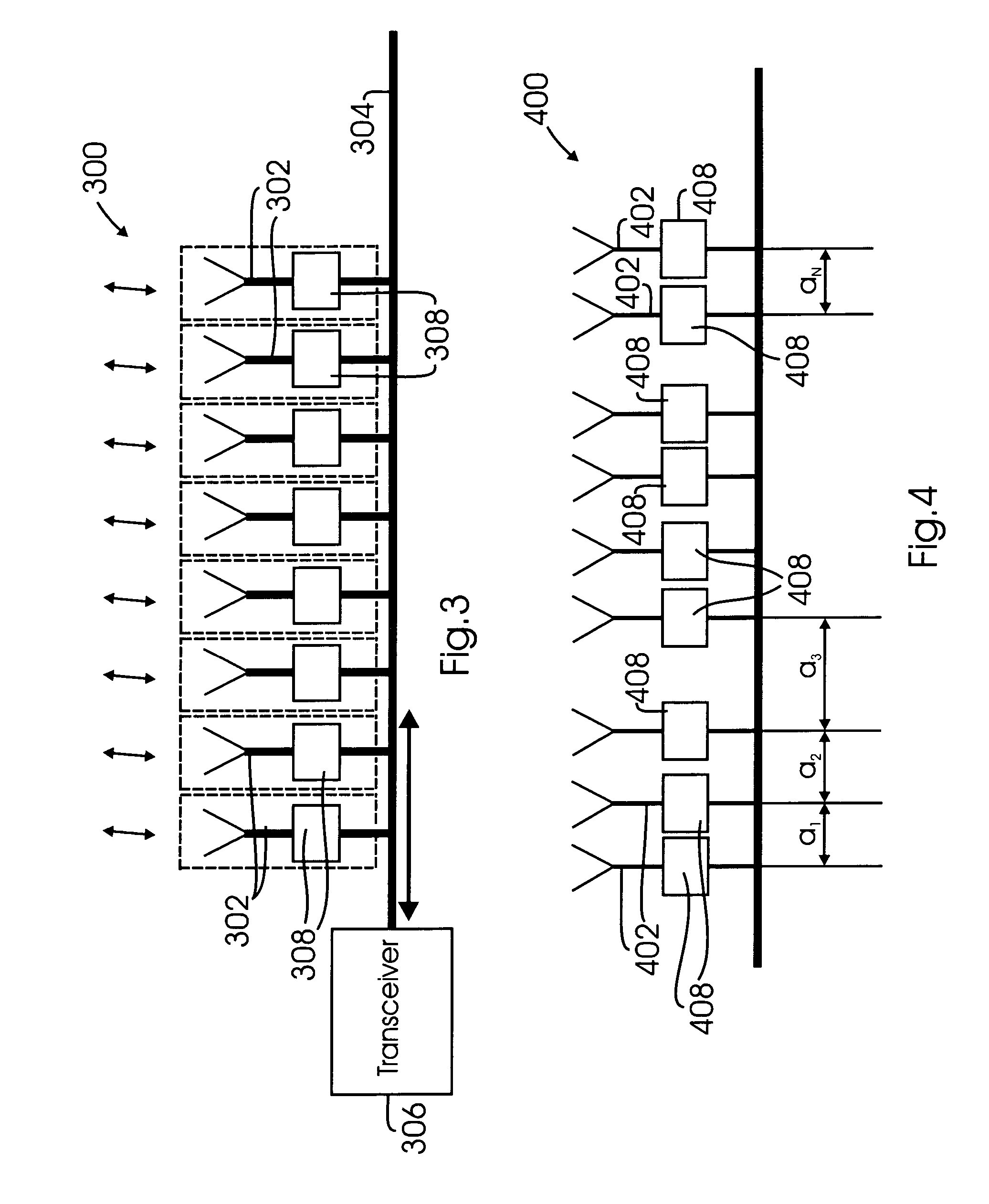
[0022]FIGS. 1, 2, and 3 respectively illustrate three configurations of a beam-forming antenna in accordance with a broad concept of the present invention. As will be described in more detail below, the beam-forming antenna in accordance with the present invention comprises at least one linear array of individual antenna elements, each of which is electromagnetically coupled to a transmission line through an amplitude controlling device, wherein the antenna elements are spaced from each other by a spacing distance that is less than or equal to one-third the wavelength, in the surrounding medium, of the electromagnetic radiation transmitted and / or received by the antenna. As shown in FIGS. 1, 2, and 3, the spacing distances between each adjacent pair of antenna elements may advantageously be equal, but as discussed below with respect to FIG. 4, these spacing distances need not be equal.

[0023]More specifically, FIG. 1 illustrates a beam-forming antenna 100 configured for transmitting ...


PUM


Abstract

A beam-forming antenna for transmission and / or reception of an electromagnetic signal having a given wavelength in a surrounding medium includes a transmission line electromagnetically coupled to an array of individually controllable antenna elements, each of which is oscillated by the signal with a controllable amplitude. The antenna elements are arranged in a linear array and are spaced from each other by a distance that does not exceed one-third the signal's wavelength in the surrounding medium. The oscillation amplitude of each of the individual antenna elements is controlled by an amplitude controlling device, such as a switch, a gain-controlled amplifier, or a gain-controlled attenuator. The amplitude controlling devices, in turn, are controlled by a computer that receives as its input the desired beamshape, and that is programmed to operate the amplitude controlling devices in accordance with a set of stored amplitude values derived empirically for a set of desired beamshapes.

Description

CROSS-REFERENCE TO RELATED APPLICATION[0001]Not ApplicableFEDERALLY SPONSORED RESEARCH OR DEVELOPMENT[0002]Not ApplicableBACKGROUND OF THE INVENTION[0003]This invention relates generally to the field of directional antennas for transmitting and / or receiving electromagnetic radiation, particularly (but not exclusively) microwave and millimeter wavelength radiation. More specifically, the invention relates to a composite beam-forming antenna comprising an array of antenna elements, wherein the shape of the transmitted or received beam is determined by controllably varying the effective oscillation amplitude of individual antenna elements. In the context of this invention, the term “beam shape ” encompasses the beam direction, which is defined as the angular location of the power peak of the transmitted / received beam with respect to at least one given axis, the beamwidth of the power peak, and the side lobe distribution of the beam power curve.[0004]Beam-forming antennas that allow for...

Claims


Application Information

Patent Timeline
Patent Type & Authority Patents(United States)
IPC IPC(8): H01Q3/22G01S1/00H01Q3/00H04B7/185G01S19/19
CPCH01Q21/22
Inventor MANASSON, VLADIMIR A.SADOVNIK, LEV S.
Owner SIERRA NEVADA CORP
Why Eureka
Try Eureka