Process control methodologies for biofuel appliance

a technology of process control and biofuel, which is applied in the direction of domestic stoves or ranges, ways, instruments, etc., can solve the problems of wasting all practical purposes of heat carried to the outside by exhaust gas, and the dynamic range of known combustion appliances is generally limited, and there is a limit to this approach

Inactive Publication Date: 2008-11-25
HESTIA HEATING PRODS
View PDF21 Cites 9 Cited by
  • Summary
  • Abstract
  • Description
  • Claims
  • Application Information

AI Technical Summary

Benefits of technology

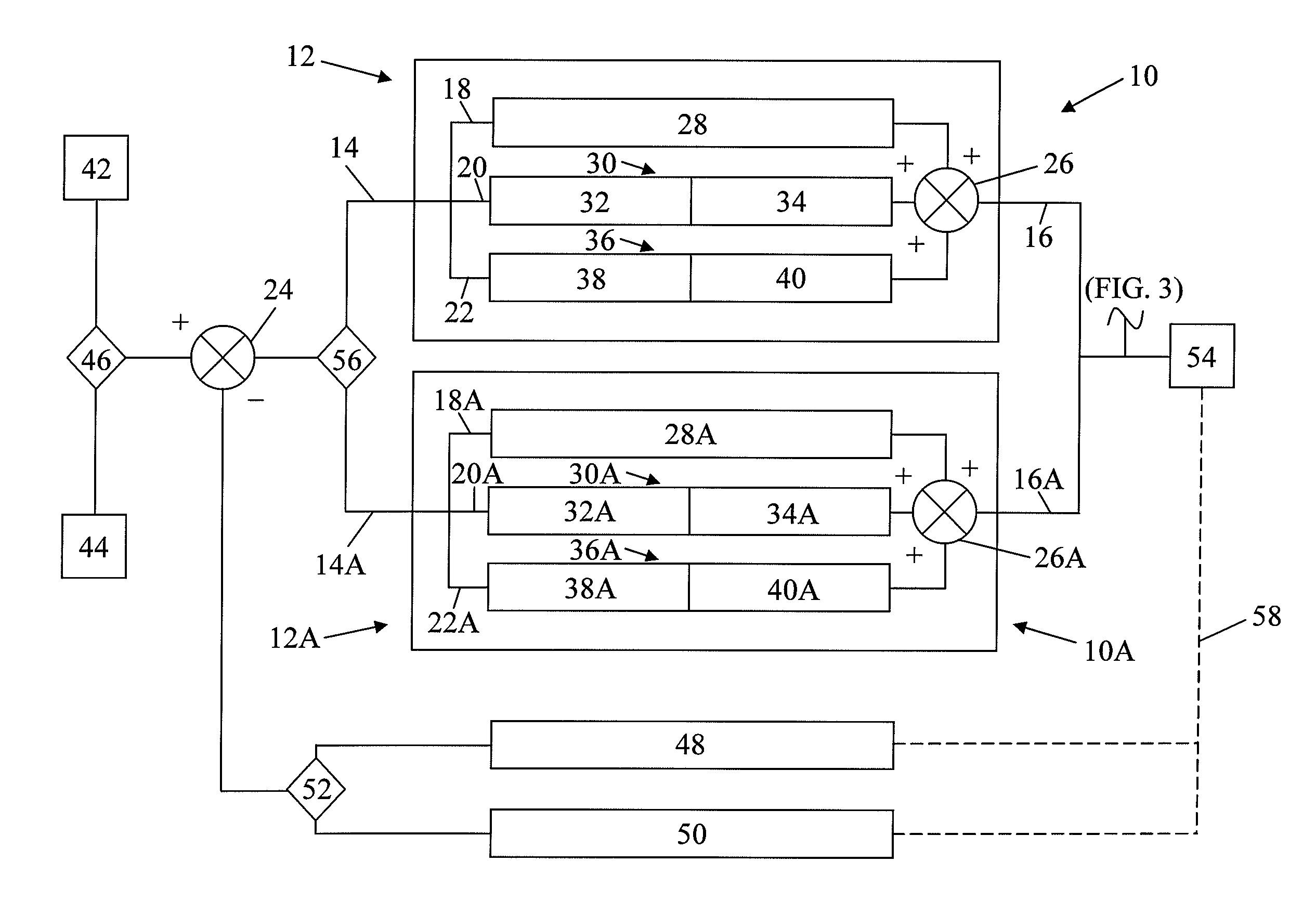
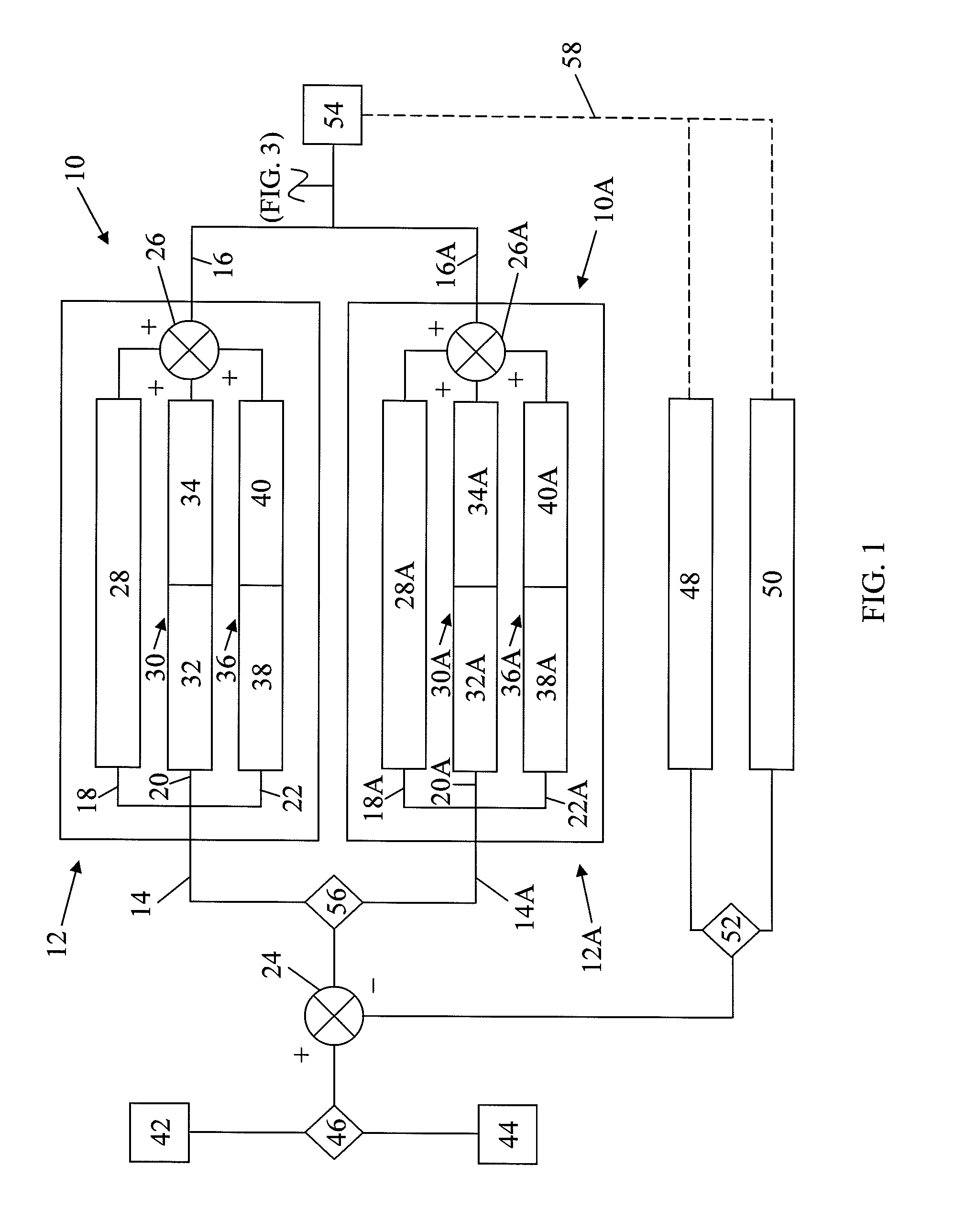
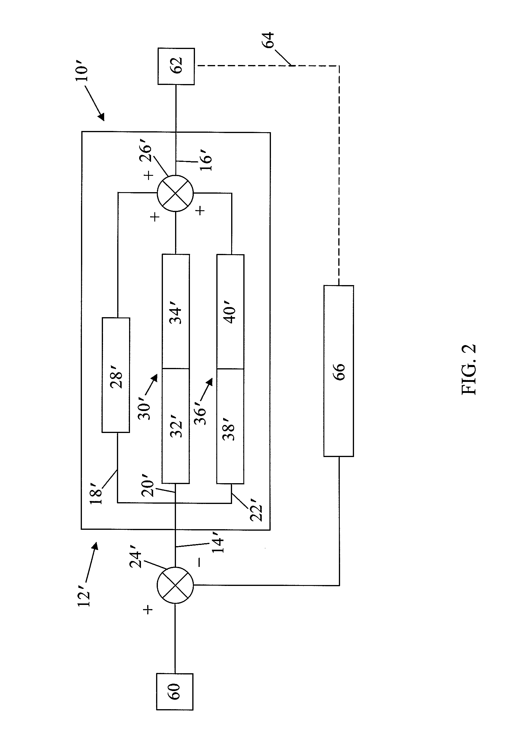
[0017]PID algorithms, which are well-known in the art and explained in a number of textbooks, require an input value which is used to calculate three output quantities. These three quantities are summed to provide the PID system output as a control. The first PID quantity applies a first gain to the input signal, the second quantity differentiates the input signal and applies a second gain to the differential, and the third quantity integrates the input signal and applies a third gain to the integral. These three outputs are summed to provide the output control signal. In a PID system, the time response can be set up to provide an essentially unlimited number of different time response curves. This permits provisions for any desired time response for the system.

Problems solved by technology

Heretofore known combustion appliances are generally limited in their dynamic range, i.e., their ability to run at both very high and very low heat outputs, even when utilizing a single, uniform fuel source, e.g., a pelletized biomass, let alone when the biofuel may be variable from one heating event to another.
Heat carried to the outside by the exhaust gas is for all practical purposes wasted.
There is however a limit to this approach.
This condensation is usually highly acidic which produces rapid deterioration of the flue.

Method used


Image

  • Process control methodologies for biofuel appliance
  • Process control methodologies for biofuel appliance
  • Process control methodologies for biofuel appliance

Examples


Embodiment Construction

[0027]A preferred, non-limiting combustion device and / or a heating appliance is generally depicted in co-pending U.S. patent application Ser. No. 11 / 550,494, filed Oct.18, 2006, entitled “Apparatus for Combustion of Biofuels,” previously incorporated herein by reference in its entirety. The PID control loops for regulating combustion parameters of said device(s), or such device(s) generally, are depicted in FIGS. 1-3, namely, the regulation of fuel feed rate in response to the selection of a target environmental ambient temperature (FIG. 1); the regulation of the convection or recirculation air throughput as a function of a preselect exhaust temperature (FIG. 2); and, the regulation of the combustion air throughput as a function of combustion efficiency, i.e., via a preselect target ratio of exhaust / heat exchanger temperature calibrated to said efficiency (FIG. 3)

[0028]In-as-much as a combination of each of the process control methodologies is especially advantageous and contemplate...


PUM


Abstract

Apparatus for controlling the operation of a biomass stove utilizes three proportional integral derivative (PID) controllers as part of a closed loop to control the fuel feed rate, the convection fan speed and the combustion fan speed. The first loop controls room temperature, the second loop controls the convection fan speed and the third loop controls the combustion fan. Appropriate temperature readings are utilized for the first and second loop. The third loop, which utilized feedback of the ratio between the heat exchanger temperature to the exhaust temperature, in addition to measuring these temperatures also references a library of look-up tables of such ratios over the entire heat range of the stove that have been correlated to combustion efficiency, as an input. This enables the operator to optimize the heat output for any operating point.

Description

TECHNICAL FIELD[0001]The present invention generally relates to biofuel burning heating devices, more particularly, to devices for the efficient production of thermal energy from biofuels such as pelletized, minimally processed, and / or raw biomass, and more particularly still, to process control methodologies for such devices.BACKGROUND OF THE INVENTION[0002]With the increasing cost of gas and fuel oil, in combination with an ever increasing social consciousness directed to conservation and recycling, further attention is being directed to alternate fuel sources such as wood and other solid / semi-solid combustibles or combustible residues. A resurgence of interest and attention is being given to biofuels, biofuel combustion processes and biofuel combustion devices.[0003]“Biofuel” is a term generally understood to embrace any fuel derived from biomass, namely, recently living organisms or their metabolic byproducts. Agricultural products specifically grown for use as biofuels include,...

Claims


Application Information

Patent Timeline
Patent Type & Authority Patents(United States)
IPC IPC(8): G05D23/00
CPCF23N5/203G05B13/0245F23N2023/36F23N2025/12F23N2039/02F23N2223/36F23N2225/12F23N2239/02
Inventor NELSON, ERIC W.MAST, MARION L.
Owner HESTIA HEATING PRODS
Why Eureka
Try Eureka