Water heater

a water heater and water tube technology, applied in indirect heat exchangers, lighting and heating apparatus, steam generation using hot heat carriers, etc., can solve the problems of water in the water tube not being discharged smoothly to the outside, water remaining in the water tube and freezing, and heat exchange efficiency deterioration

Inactive Publication Date: 2008-12-02
NORITZ CORP
View PDF19 Cites 34 Cited by
  • Summary
  • Abstract
  • Description
  • Claims
  • Application Information

AI Technical Summary

Problems solved by technology

Since such primary heat exchanger is not acid-resistant, the primary heat exchanger needs to be so designed that strongly acidic condensate water is not formed accompanying the heat recovery.
First, when the driving of the water heater is stopped in winter, it is desired to prevent the interior of the water tube of the heat exchanger from freezing. To prevent the freezing without using an antifreeze heater, it is necessary to drain water from the water tube after the water inflow to the water tube is stopped. Such draining of water may be sometimes necessary also at the time of maintenance of the water heater. Since the water tube of the primary heat exchanger has a relatively large diameter, water in the water tube can be smoothly discharged to the outside. In the secondary heat exchanger, however, the diameter of the water tube is relatively small, as noted above. Therefore, due to the surface tension of water generated in the water tube, the water in the water tube may not be smoothly discharged to the outside. As a result, water remains in the water tube and freezes.
Secondly, when condensate water remains adhering to a wide range of the surface of a water tube of the secondary heat exchanger, the heat exchange between the water tube and the combustion gas is hindered by the condensate water, whereby the heat exchange efficiency is deteriorated. Conversely, when much condensate water drops down from a water tube of the secondary heat exchanger, the primary heat exchanger is contaminated and corroded due to the condensate water dropped from the secondary heat exchanger in the case where the primary heat exchanger is arranged directly under the secondary heat exchanger.
However, since the driving of the water heater is not constant, much condensate water may be formed at a surface of the water tube of the secondary heat exchanger.
Further, all amounts of the condensate water may not be evaporated before reaching the lower end of the water tube.
In such a case, unevaporated condensate water may reach the lower end of the water tube to flow below to contaminate the adjacent portions.
Moreover, although the water tube is inclined in the water heater of the Patent Document 5, specific measures are not taken to properly drain water from the water tube.
Therefore, the draining of water to prevent freezing, for example, cannot be performed easily and properly.

Method used


Image

  • Water heater
  • Water heater
  • Water heater

Examples


Embodiment Construction

[0035]Preferred embodiments of the present invention will be described below with reference to the accompanying drawings.

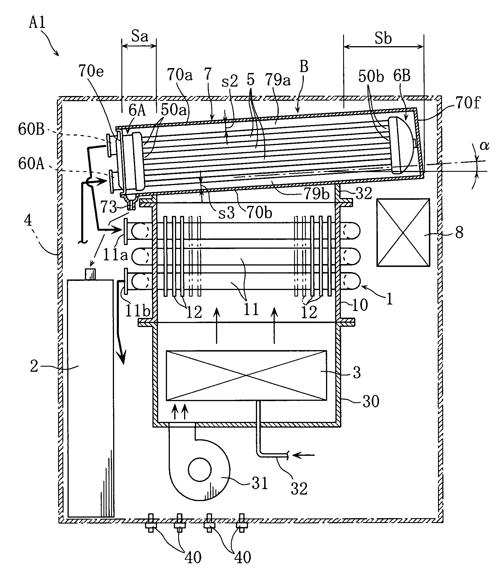
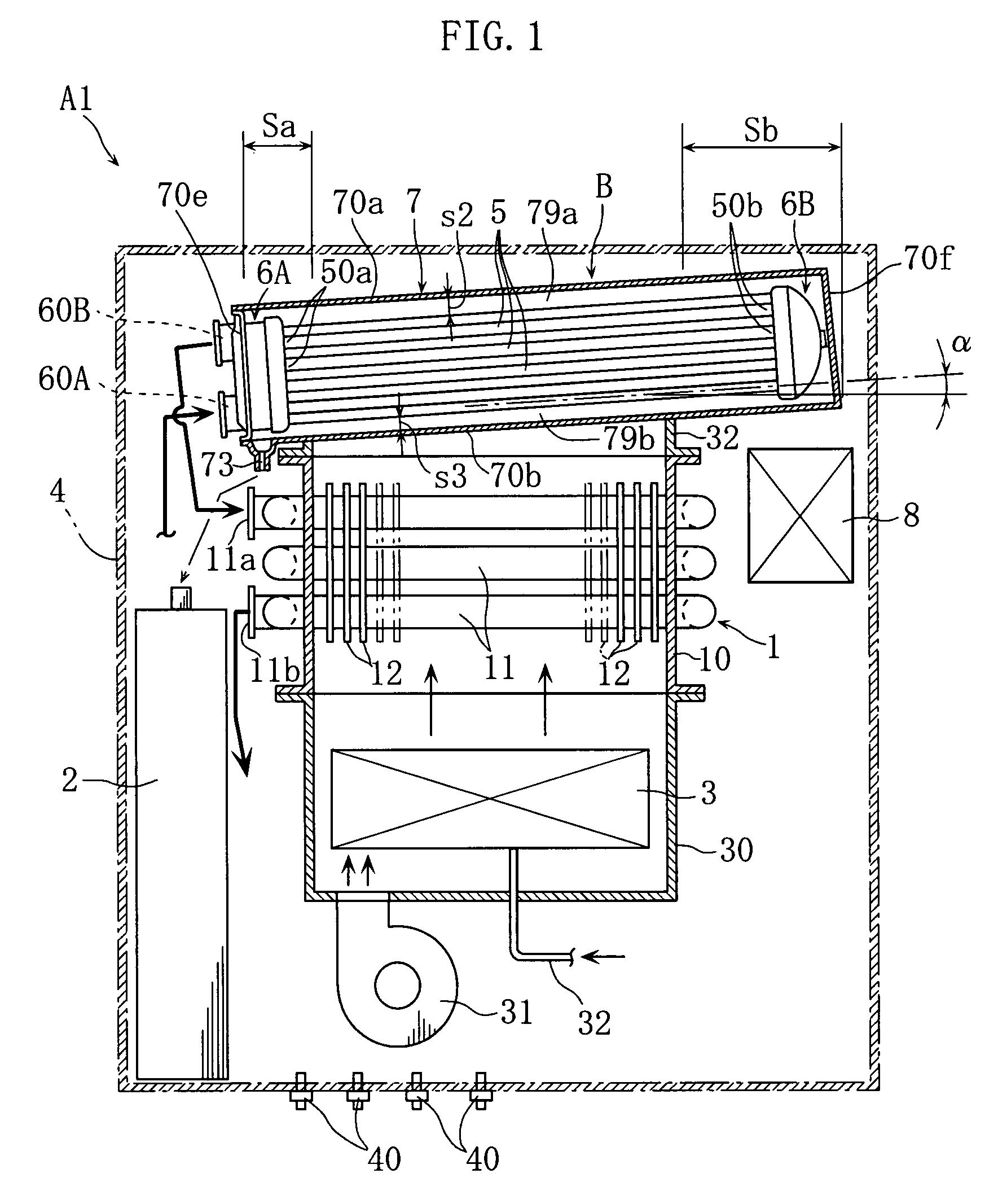
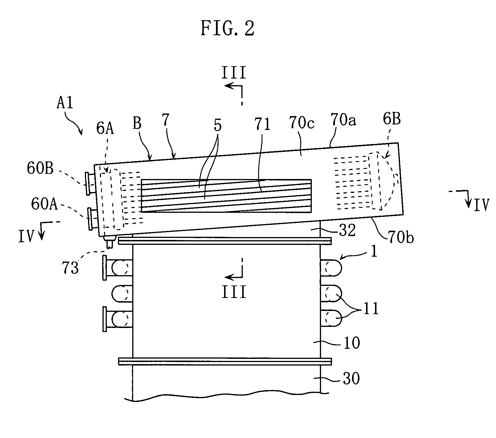
[0036]FIGS. 1-8 show an embodiment of water heater according to the present invention. As better shown in FIG. 1, the water heater A1 of this embodiment includes a burner 3, a primary heat exchanger 1, a secondary heat exchanger B, a neutralizer 2, and an external casing 4 for enclosing these parts.

[0037]The burner 3, which is arranged in a housing 30 having an upper open end, is a gas burner for burning fuel gas supplied through a pipe 32. A fan 31 is arranged below the housing so that air for combustion is supplied from the fan upward into the housing 30. The basic structure of the primary heat exchanger 1 is similar to that of conventionally known heat exchangers and includes a water tube 11 provided with a plurality of fins 12 and penetrating through the housing 10 in a generally horizontal direction. On the housing 30 of the burner 3, a housing 10 is mounted....


PUM


Abstract

A secondary heat exchanger B for recovering latent heat from combustion gas includes water tubes 5 each of which is so inclined that a first end 50a is positioned lower than a second end 50b. Therefore, in draining water from each of the water tubes 5, water can be caused to flow smoothly into a water-inflow and hot-water-outflow header 6A connected to the first ends 50a. The secondary heat exchanger B includes a casing 7 which includes an upper wall 70a and a bottom wall 70b which are so inclined that the inner surfaces thereof extend generally in parallel with the water tubes 5, and the upper and the lower gaps 79a and 79b have constant widths s2 and s3. Therefore, the amount of heat recovery from the combustion gas passing through the gaps 79a and 79b can be increased.

Description

TECHNICAL FIELD[0001]The present invention relates to a water heater for producing hot water by generating combustion gas by a burner and recovering heat from the combustion gas by a heat exchanger.BACKGROUND ART[0002]Some water heaters include a secondary heat exchanger for recovering latent heat in addition to a primary heat exchanger for recovering sensitive heat (See Patent Documents 1-4, for example). With this structure, the heat exchange efficiency can be enhanced as compared with the structure designed to recover only sensitive heat from combustion gas. However, when latent heat is recovered from combustion gas, water vapor contained in the combustion gas condenses to form condensate water. Generally, condensate water having absorbed sulfur oxide, nitrogen oxide and so on contained in the combustion gas has a strong acidity of about pH 3.[0003]In the above-described water heater, the secondary heat exchanger may be made of e.g. acid-resistant stainless steel so as not to be ...

Claims


Application Information

Patent Timeline
Patent Type & Authority Patents(United States)
IPC IPC(8): F22B1/02
CPCF24H1/40F24H8/00F28F17/005Y02B30/102F28D7/1638Y02B30/00
Inventor TAKEDA, NOBUHIROASAKURA, HIROSHITSUTSUMI, AKIRAKIMURA, KAZUHIROKAMEYAMA, SHUJIAMADA, KEIICHIMATSUNAGA, HIRONAO
Owner NORITZ CORP
Why Eureka
Try Eureka