
Mold assembly for manufacturing a masonry block

a technology of masonry blocks and molds, applied in the field of mold assembly for manufacturing masonry blocks, can solve the problems of difficult to impart a natural appearance to the face of concrete blocks, and achieve the effect of simple pattern

Inactive Publication Date: 2008-12-02
ANCHOR WALL SYST INC
View PDF83 Cites 37 Cited by
  • Summary
  • Abstract
  • Description
  • Claims
  • Application Information

AI Technical Summary

Benefits of technology

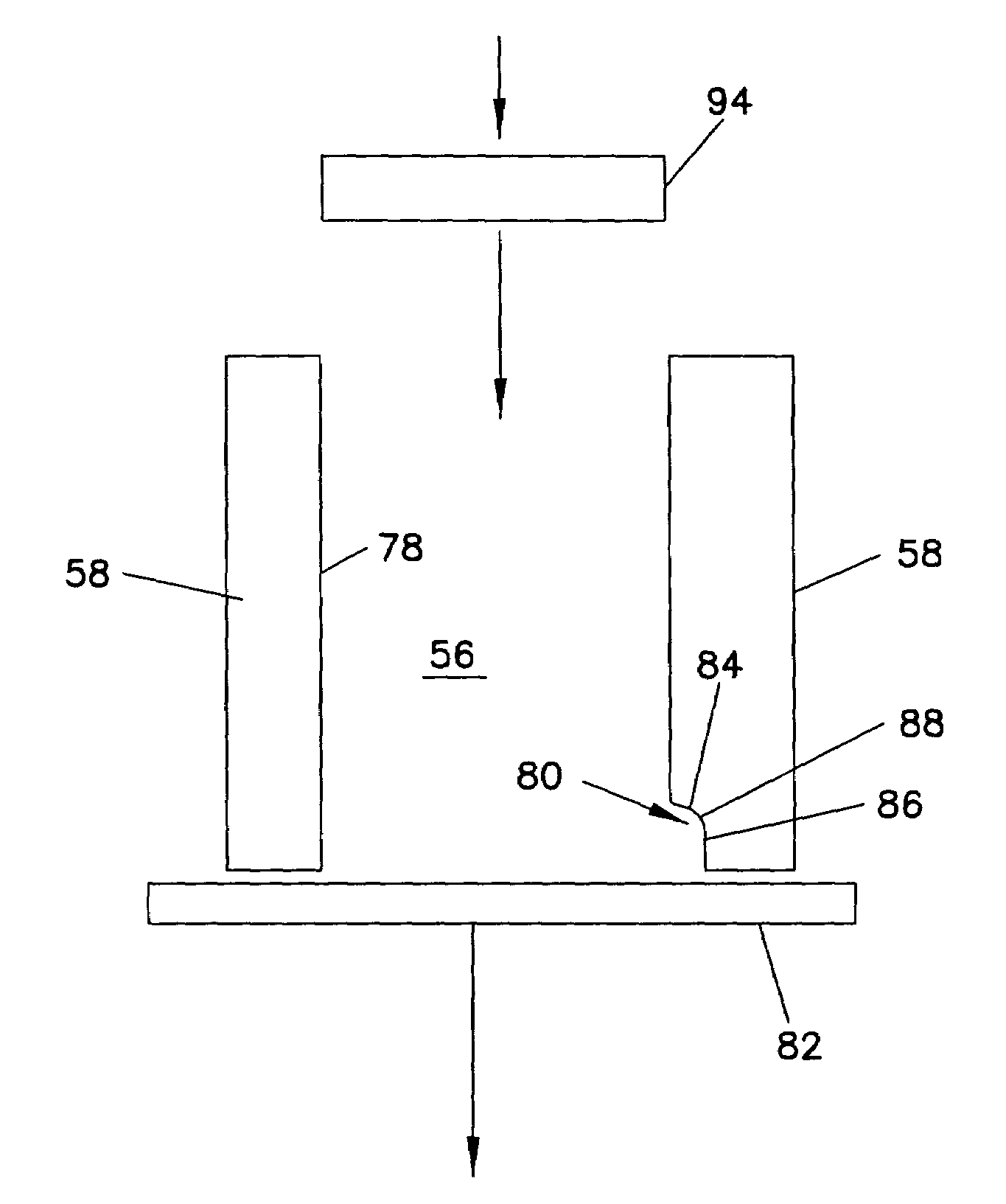
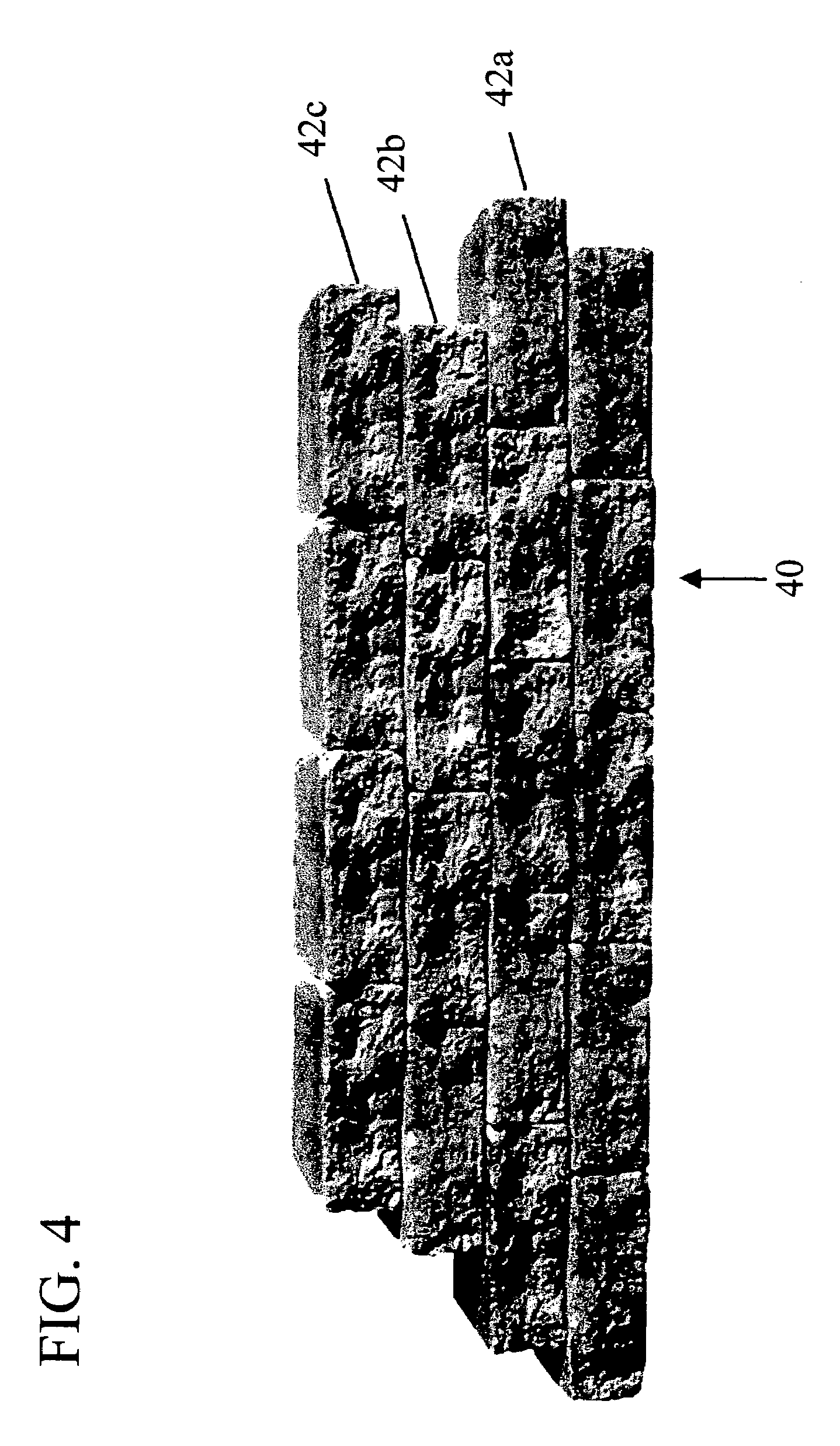
[0008]One aspect of this invention is that a mold made in accordance with the invention is arranged so that the portion of the block that will be the front face when the block is laid is facing the open top of the mold cavity during the molding process. This orientation permits the front face of the block to be formed by the action of a patterned pressure plate (“stripper shoe”) in a high-speed, masonry block or paver plant. The stripper shoe can be provided with a very simple pattern, a moderately complex pattern, or a highly detailed, three-dimensional pattern with significant relief, simulating naturally occurring stone. Molding the block in this orientation also makes the block face readily accessible for other processing to affect the appearance of the face, including the application of specially-selected aggregate and / or color pigments to the face.

Problems solved by technology

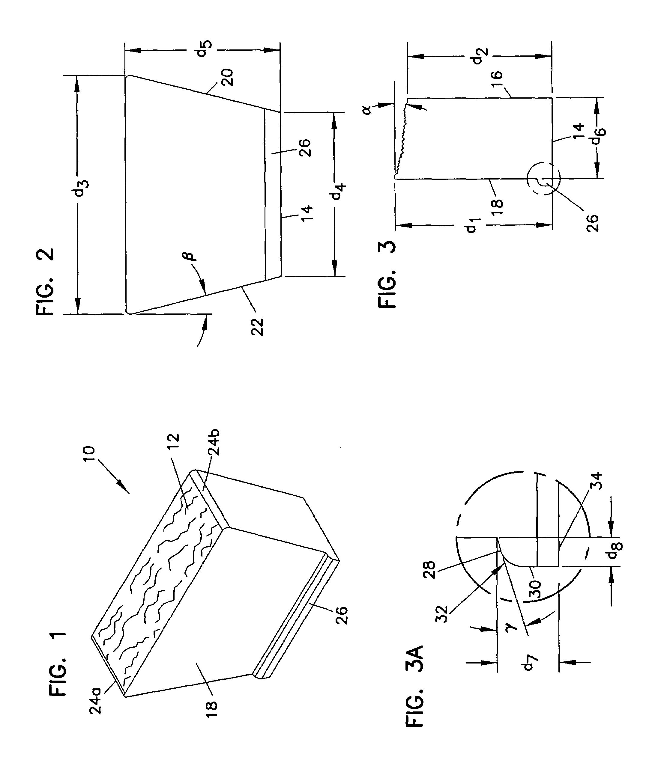
Due to the nature of such plants and the equipment used to perform this process, it is difficult to impart a natural appearance to the face of a concrete block, particularly if the block needs to include other features, such as converging side walls, and an integral locator / shear flange(s) formed on the top and / or bottom face of the block.

Method used


Image

  • Mold assembly for manufacturing a masonry block
  • Mold assembly for manufacturing a masonry block
  • Mold assembly for manufacturing a masonry block

Examples


Embodiment Construction

Overview

[0025]The present invention provides a process for producing a concrete masonry block, as well as a block resulting from the process, and a mold and mold components used to implement the process, in which a pre-determined three-dimensional pattern is impressed into the face of the block, and the front face of the block can be otherwise directly processed or worked so that a pre-determined block front face can be produced in a standard dry cast concrete block or paver machine. Direct processing or working of the front face includes molding, shaping, patterning, impressing, material layering, combinations thereof, and other processes in which the texture, shape, color, appearance, or physical properties of the front face can be directly affected. Further, the process can be implemented using multiple-cavity molds to permit high-speed, high-volume production of the masonry blocks on standard dry cast concrete block or paver equipment. Moreover, use of the inventive process and ...


PUM

PropertyMeasurementUnit
width d3aaaaaaaaaa
radiusaaaaaaaaaa
width d4aaaaaaaaaa

Abstract

Molds and processes that permit high-speed, mass production of retaining wall blocks having patterned or other processed front faces, as well as retaining wall blocks formed by such processes. The invention permits the front face of the block to be impressed with a pattern or otherwise directly processed, to allow the formation of pre-determined block front faces, while at the same time facilitating high-speed, high-volume production of blocks. Pre-determined front faces can include front faces having pre-determined patterns and textures, front faces having pre-determined shapes, front faces made from different material(s) than the remainder of the block, and combinations thereof.

Description

[0001]This application is a continuation of application Ser. No. 10 / 038,639, filed Jan. 4, 2002, now U.S. Pat. No. 7,140,867, issued Nov. 28, 2006. Application Ser. No. 10 / 038,639 is incorporated by reference hereinFIELD OF THE INVENTION[0002]The invention relates generally to concrete masonry blocks and the manufacture thereof. More specifically, the invention relates to concrete masonry blocks suitable for use in landscaping applications, such as retaining walls, and manufacturing processes useful in the production of such blocks.BACKGROUND OF THE INVENTION[0003]Modern, high speed, automated concrete block plants and concrete paver plants make use of molds that are open at the top and bottom. These molds are mounted in machines which cyclically station a pallet below the mold to close the bottom of the mold, deliver dry cast concrete into the mold through the open top of the mold, densify and compact the concrete by a combination of vibration and pressure, and strip the mold by a ...

Claims


Application Information

Patent Timeline
Patent Type & Authority Patents(United States)
IPC IPC(8): B28B7/20B28B3/02E02D29/02B28B3/08B28B7/00B28B7/10B28B7/34B28B7/38E04B2/02E04C1/39
CPCB28B7/007B28B7/0097E04C1/395B28B7/0044B28B7/20B28B7/38E04B2002/0269Y10S425/058E04C1/39E04C1/00B28B7/00
Inventor SCHERER, RONALD J.LACROIX, DAVID M.BAILEY, PAUL W.
Owner ANCHOR WALL SYST INC
Learn More