Microstrip type bandpass filter

a bandpass filter and microstrip technology, applied in the direction of waveguides, resonators, electrical equipment, etc., can solve the problems of limited design based on dielectric coefficient and difficulty in implementing a bandpass filter having a minimum width of 2.0 mm or less, so as to achieve easy mass production and reduce manufacturing costs

Inactive Publication Date: 2006-04-20
ELECTRONICS & TELECOMM RES INST
View PDF7 Cites 9 Cited by
  • Summary
  • Abstract
  • Description
  • Claims
  • Application Information

AI Technical Summary

Benefits of technology

[0033] The present invention is directed to a microstrip type bandpass filter, in which an electric coupling physically coupled in parallel is provided between the input / output terminal and the resonator and between the resonators, and a magnetic coupling is provided using a cross coupling gap or a cross coupling line between non-adjacent resonators, so that a pattern can be simplified by optimizing the design and the manufacturing process to provide low-cost millimeter-wave parts, the manufacturing cost can be reduced by miniaturizing the parts, and the mass production can be readily realized.

Problems solved by technology

However, although the open loop resonator is suitable for a wireless communication system adapted to a high selectivity channeling and low insertion loss, only one attenuation pole is formed and a design is limited based on the dielectric coefficient.
According to the prior arts, it is difficult to implement a bandpass filter having a minimum width of 2.0 mm or less.

Method used


Image

  • Microstrip type bandpass filter
  • Microstrip type bandpass filter
  • Microstrip type bandpass filter

Examples


first embodiment

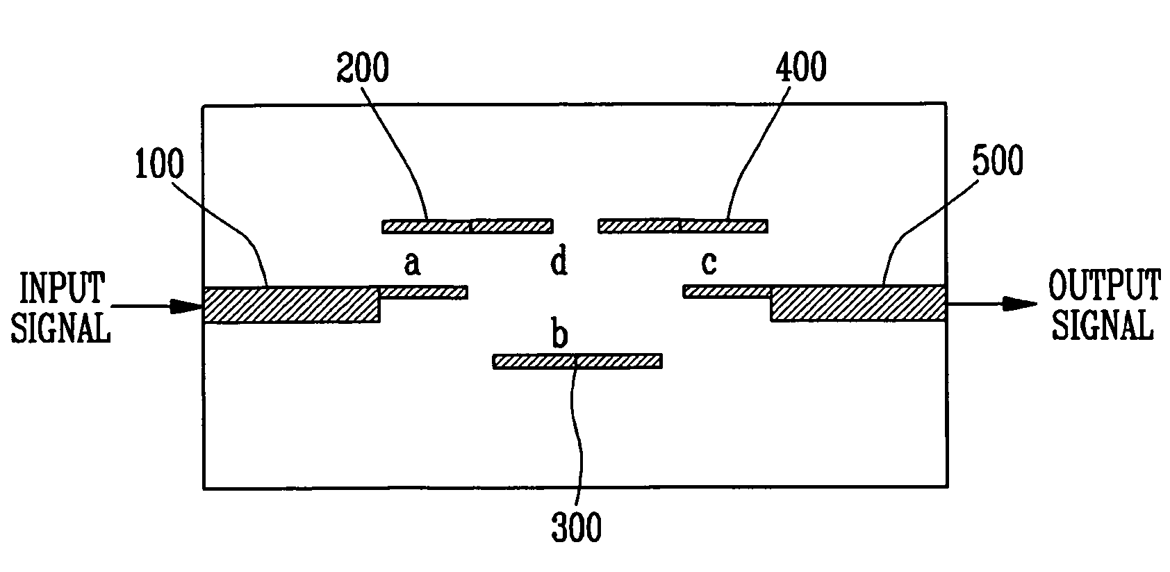
[0056]FIG. 5 is a pattern diagram for illustrating a microstrip type bandpass filter according to a first embodiment of the present invention, which is a pattern diagram of a bandpass filter having a microstrip type asymmetric frequency characteristic and formed with a cross coupling and a λ / 2 transmission line resonator.

[0057] Referring to FIG. 5, the microstrip type bandpass filter according to the first embodiment of the present invention comprises an input terminal 100, first to third resonators 200 to 400, and an output terminal 500.

[0058] Here, the microstrip type bandpass filter according to the first embodiment of the present invention is a type of a parallel coupling filter, in which there are provided an electric coupling (a) between the input terminal 100 and the first resonator 200, an electric coupling (b) between the first resonator 200 and the second resonator 300 and between the second resonator 300 and the third resonator 400, and an electric coupling (c) between ...

second embodiment

[0067]FIG. 7 is a pattern diagram for illustrating a microstrip type bandpass filter according to a second embodiment of the present invention, in which like numerals refer to like elements with respect to the identical portions to the microstrip type bandpass filter according to the first embodiment of the present invention shown in FIG. 5, i.e., the input terminal 100, the first to third resonators 200 to 400, the output terminal 500 and the electric couplings (a) to (c) and the cross coupling gap (d).

[0068] Referring to FIG. 7, the microstrip type bandpass filter according to the second embodiment of the present invention is formed with a cross coupling having a microstrip type symmetric frequency characteristic and a λ / 2 transmission line resonator. In particular, the microstrip type bandpass filter according to the second embodiment of the present invention further comprises cross couplings (e) and (f) of the cross coupling line 600.

[0069] Here, there are provided an electric...


PUM


Abstract

Provided is a narrowband microstrip type bandpass filter adapted- to a home network, telematics, an intelligent traffic system, and a satellite Internet, the microstrip type bandpass filter comprising: an input terminal for receiving a predetermined signal; an output terminal for outputting a selection signal in a characteristic band; a first resonator electrically coupled with at least a portion of the input terminal; a second resonator electrically coupled with at least a portion of the first resonator; and a third resonator electrically coupled with at least a portion of the output terminal and the second resonator, and a magnetic coupling is provided using a cross coupling gap or a cross coupling line between non-adjacent resonators, so that a pattern can be simplified by optimizing the design and the manufacturing process to provide low-cost millimeter-wave parts, the manufacturing cost can be reduced by miniaturizing the parts, and the mass production can be readily realized.

Description

CROSS-REFERENCE TO RELATED APPLICATION [0001] This application claims priority to and the benefit of Korean Patent Application No. 2004-83337, filed Oct. 18, 2004, the disclosure of which is hereby incorporated herein by reference in its entirety. BACKGROUND [0002] 1. Field of the Invention [0003] The present invention relates to a narrowband microstrip type bandpass filter adapted to a home network, telematics, an intelligent traffic system, and a satellite Internet and, more specifically, to a microstrip type bandpass filter, in which a pattern can be simplified by optimizing the design and the manufacturing process to provide low-cost millimeter-wave parts, the manufacturing cost can be reduced by miniaturizing the parts, and the mass production can be readily realized. [0004] 2. Discussion of Related Art [0005] Recently, a millimeter-wave application has been proposed in a field such as a home network, telematics, an intelligent traffic system and a satellite Internet. To succee...

Claims


Application Information

Patent Timeline
Patent Type & Authority Applications(United States)
IPC IPC(8): H01P1/203
CPCH01P1/203H01P7/08H01P1/20
Inventor JUN, DONG SUKLEE, HONG YEOLKIM, DONG YOUNGCHO, KYOUNG IKLEE, SANG SEOK
Owner ELECTRONICS & TELECOMM RES INST
Why Eureka
Try Eureka