Continuous process for manufacturing electrical cables

a manufacturing process and technology for electrical cables, applied in the direction of power cables, cables, insulation conductors/cables, etc., can solve the problems of increasing introducing space and logistic problems, and prolonging the cable manufacturing time, so as to increase the cost of cable production and extend the cable manufacturing time.

Inactive Publication Date: 2008-12-02
PRYSMIAN CAVI E SISTEMI ENERGIA
View PDF19 Cites 25 Cited by
  • Summary
  • Abstract
  • Description
  • Claims
  • Application Information

AI Technical Summary

Benefits of technology

[0025]The Applicant has perceived that the presence of a rest phase during the cable production, for example for curing or degassing purposes, is undesirable because it limits the length of each cable piece (storage on cable reels being required), it introduces space and logistic problems in the factory, it extends the cable manufacturing time and, finally, it increases the cost of the cable production.
[0039]Furthermore, the Applicant has found that the cable obtained by the continuous process of the present invention is surprisingly provided with high mechanical resistance to accidental impacts which may occur on the cable.
[0041]Furthermore, the Applicant has noticed that, in case a deformation of the shield occurs due to a relevant impact on the cable, the presence of a circumferentially closed metal shield is particularly advantageous since the shield deforms continuously and smoothly, thereby avoiding any local increases of the electric field in the insulating layer.
[0042]Moreover, the Applicant has found that a cable provided with a thermoplastic insulating layer, a circumferentially closed metal shield and an impact protecting element comprising at least one expanded polymeric layer can be advantageously obtained by means of a continuous manufacturing process.
[0043]Furthermore, the Applicant has found that the mechanical resistance to accidental impacts can be advantageously increased by providing the cable with a further expanded polymeric layer in a position radially internal with respect to the metal shield.

Problems solved by technology

The Applicant has perceived that the presence of a rest phase during the cable production, for example for curing or degassing purposes, is undesirable because it limits the length of each cable piece (storage on cable reels being required), it introduces space and logistic problems in the factory, it extends the cable manufacturing time and, finally, it increases the cost of the cable production.

Method used


Image

  • Continuous process for manufacturing electrical cables
  • Continuous process for manufacturing electrical cables
  • Continuous process for manufacturing electrical cables

Examples


example 1

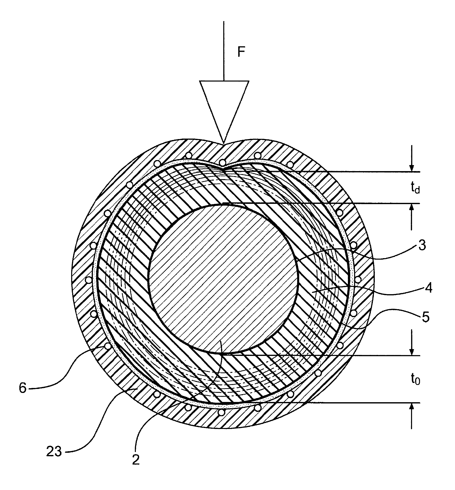
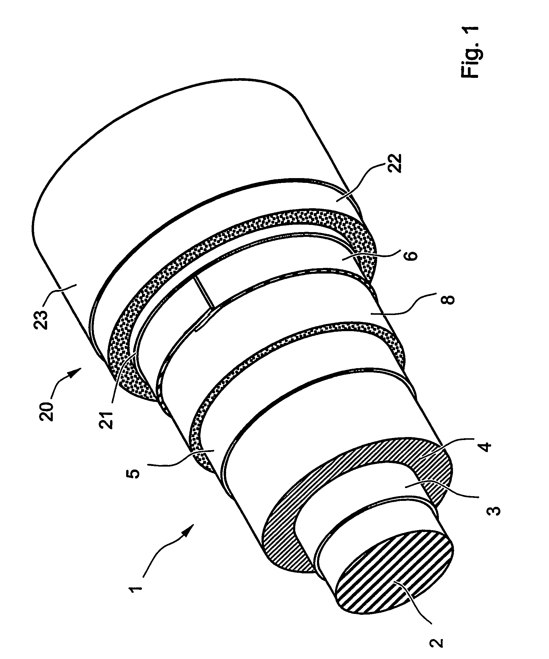
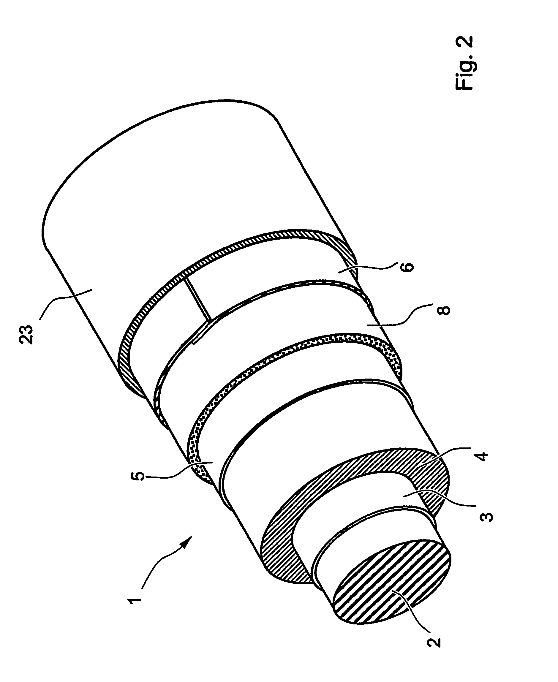
[0162]The following example describes in detail the main steps of a continuous production process of a 150 mm2, 20 kV cable according to FIG. 1. The line speed is set at 60 m / min.

a) Cable Core Extrusion

[0163]The cable insulating layer is obtained by feeding directly into the hopper of the extruder 110 a propylene heterophase copolymer having melting point 165° C., melting enthalpy 30 J / g, MFI 0.8 dg / min and flexural modulus 150 MPa (Adflex® Q 200 F—commercial product of Basell).

[0164]Subsequently, the dielectric oil Jarylec® Exp3 (commercial product of Elf Atochem—dibenzyltoluene), previously mixed with the antioxidants, is injected at high pressure into the extruder.

[0165]The extruder 110 has a diameter of 80 mm and an L / D ratio of 25.

[0166]The injection of the dielectric oil is made during the extrusion at about 20 D from the beginning of the screw of the extruder 110 by means of three injections point on the same cross-section at 120° from each other. The dielectric oil is inject...


PUM

PropertyMeasurementUnit
voltagesaaaaaaaaaa
voltagesaaaaaaaaaa
voltagesaaaaaaaaaa

Abstract

A process for manufacturing an electric cable. In particular, the process includes the steps of: a) feeding a conductor at a predetermined feeding speed; b) extruding a thermoplastic insulating layer in a position radially external to the conductor; c) cooling the extruded insulating layer; and d) forming a circumferentially closed metal shield around the extruded insulating layer. The process may be carried out continuously, i.e., the time occurring between the end of the cooling step and the beginning of the shield forming step is inversely proportional to the feeding speed of the conductor.

Description

CROSS REFERENCE TO RELATED APPLICATION[0001]This application is a national phase application based on PCT / EP2003 / 008194, filed Jul. 25, 2003, the content of which is incorporated herein by reference.BACKGROUND OF THE INVENTION[0002]1. Field of the Invention[0003]The present invention relates to a process for manufacturing electrical cables, in particular electrical cables for power transmission or distribution at medium or high voltage.[0004]In the present description, the term medium voltage is used to refer to a tension typically from about 1 kV to about 60 kV and the term high voltage refers to a tension above 60 kV (very high voltage is also sometimes used in the art to define voltages greater than about 150 kV or 220 kV, up to 500 kV or more).[0005]Said cables may be used for both direct current (DC) or alternating current (AC) transmission or distribution.[0006]2. Description of the Related Art[0007]Cables for power transmission or distribution at medium or high voltage genera...

Claims


Application Information

Patent Timeline
Patent Type & Authority Patents(United States)
IPC IPC(8): H01B7/00H01B7/18H01B13/00H01B13/14H01B13/26
CPCH01B7/189H01B13/00H01B13/14H01B13/262H01B13/2626H01B13/0003H01B9/027
Inventor BELLI, SERGIOBAREGGI, ALBERTODELL'ANNA, GAIASCELZA, CRISTIANADONAZZI, FABRIZIO
Owner PRYSMIAN CAVI E SISTEMI ENERGIA
Why Eureka
Try Eureka