

Vibration compensation apparatus using a coordinate conversion
a technology of coordinate conversion and vibration compensation, which is applied in the field of vibration compensation apparatus, can solve the problems of affecting the layout of the angular velocity detector b>1001/b>, the major cause of the degradation of the sensed image, and the limited freedom of the mount position of the sensor, etc., and achieves the effect of reducing the restriction
- Summary
- Abstract
- Description
- Claims
- Application Information
AI Technical Summary
Benefits of technology
Problems solved by technology
Method used
Image

Examples
first embodiment
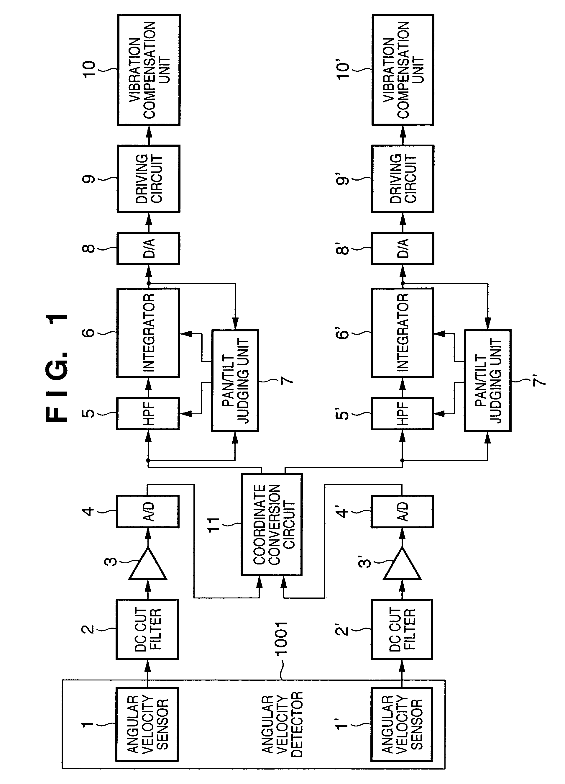
[0031]FIG. 1 shows a configuration of an image sensing apparatus according to an first embodiment of the present inventions. In the first embodiment, after an angular velocity signals are corrected by a coordinate conversion circuit for inclination amounts of an angular velocity detection axes with respect to vibration compensation axes, vibration compensation processing is performed.
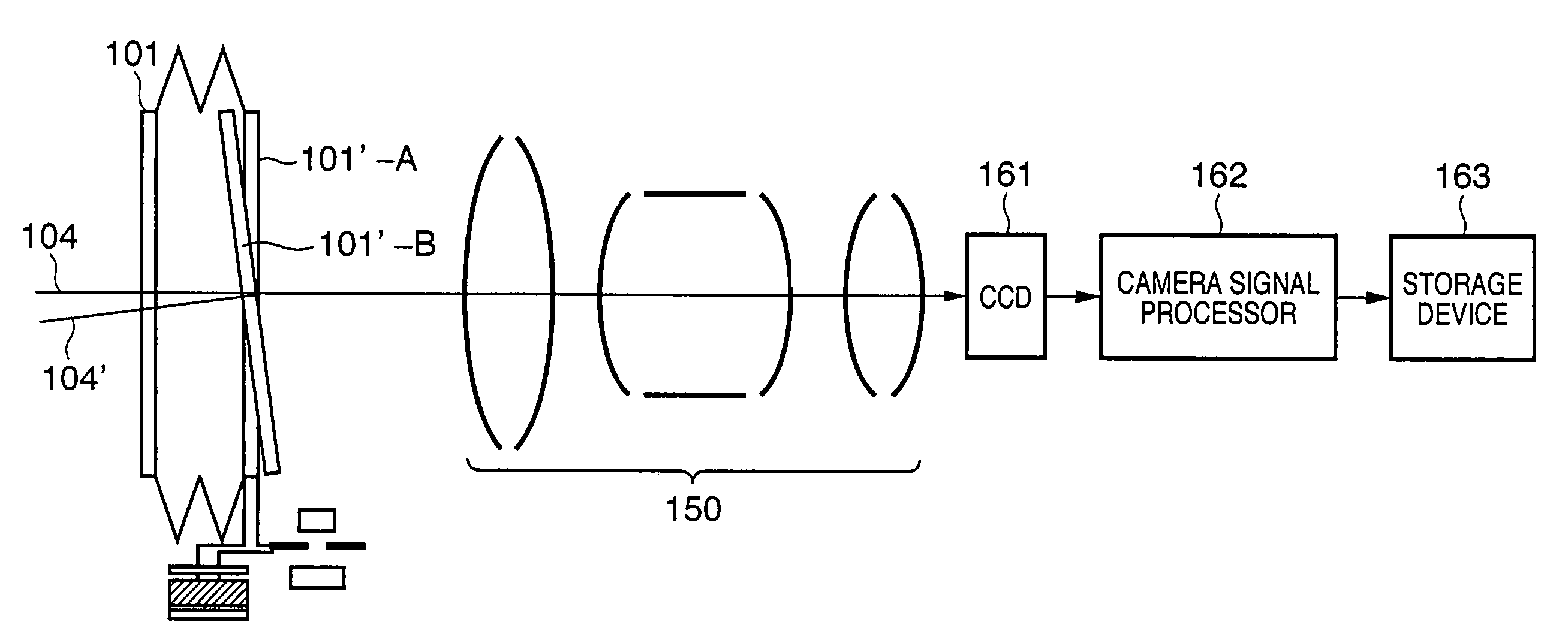
[0032]Referring to FIG. 1, reference numeral 1001 denotes an angular velocity detector having two orthogonal angular velocity axes and comprising angular velocity sensors such as, inter alia, vibration gyros. Two angular velocity sensors 1 and 1′ are packaged in the angular velocity detector 1001, with the angular velocity detection axes of the angular velocity sensors 1 and 1′ being orthogonal to each other. The angular velocity detector 1001 is mounted on an image sensing apparatus main body, such as a camera, which has a vibration compensation function to detect vibration of the apparatus as angular ...
second embodiment
[0085]FIG. 6 shows the configuration of an image sensing apparatus according to the second embodiment of the present invention. In FIG. 6, the same elements as those shown in FIG. 1 are referred to by the same reference numerals, and explanations are omitted.
[0086]As shown in FIG. 6, the coordinate conversion circuit 11 is arranged in the downstream of the integrators 6 and 6′. By arranging in this manner, a dynamic range of a signal required by the coordinate conversion circuit 11 can be narrower than that required in the arrangement of the first embodiment, it is possible to reduce the data length to be dealt with by the coordinate conversion circuit 11. This is due to an operation of the pan / tilt judging units 7 and 7′, and the characteristics of the HPFs 5 and 5′ are changed in accordance with the panning or tilting control as described above, and the values accumulated in the integrator 6 and 6′ are limited. Therefore, by arranging as described in FIG. 6, it is possible to shor...
third embodiment
[0087]In the third embodiment, an example that an operation performed in the coordinate conversion circuit 11 is simplified is explained with reference to FIG. 7. FIG. 7 is a block diagram showing an internal configuration of the coordinate conversion circuit 11. Reference numerals 311 and 312 are input terminals of vibration detection signals, and angular velocity signals which are multiplied by predetermined values are inputted.
[0088]Reference numerals 313 and 314 are output terminals of vibration compensation signals, and signals undergone the coordinate conversion (tilted amount correction) described in the first embodiment are outputted.
[0089]Reference numeral 301 denotes a storage unit such as a memory; and 302 a look-up table (LUT). The storage unit 301 stores address data indicative of addresses of the data stored in the LUP 302. LUT 302 outputs the data corresponding to the address stored in the storage unit 301. In the third embodiment, it is assumed that data is arranged ...
PUM
 Abstract
Description
Claims
Application Information