
Driveline shift quality in variable valve engine equipped drivelines

a variable valve engine and shift quality technology, applied in the direction of machines/engines, mechanical equipment, non-mechanical valves, etc., can solve the problems of large deviation in transmission output torque, increased fuel consumption and emissions, and the general decrease of engine output torque by spark retardation, so as to improve the consistency of shift to shift and improve the drive feel

Inactive Publication Date: 2008-12-09
FORD GLOBAL TECH LLC
View PDF12 Cites 6 Cited by
  • Summary
  • Abstract
  • Description
  • Claims
  • Application Information

AI Technical Summary

Benefits of technology

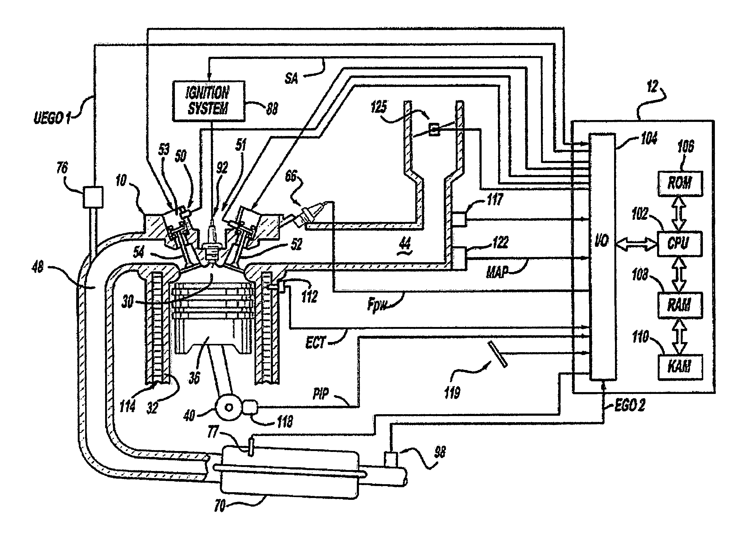
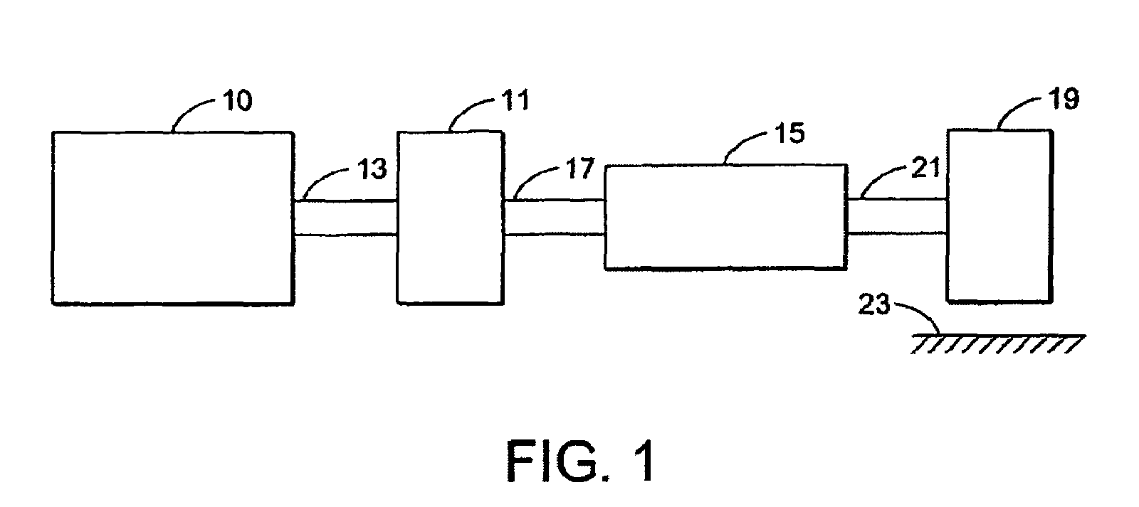
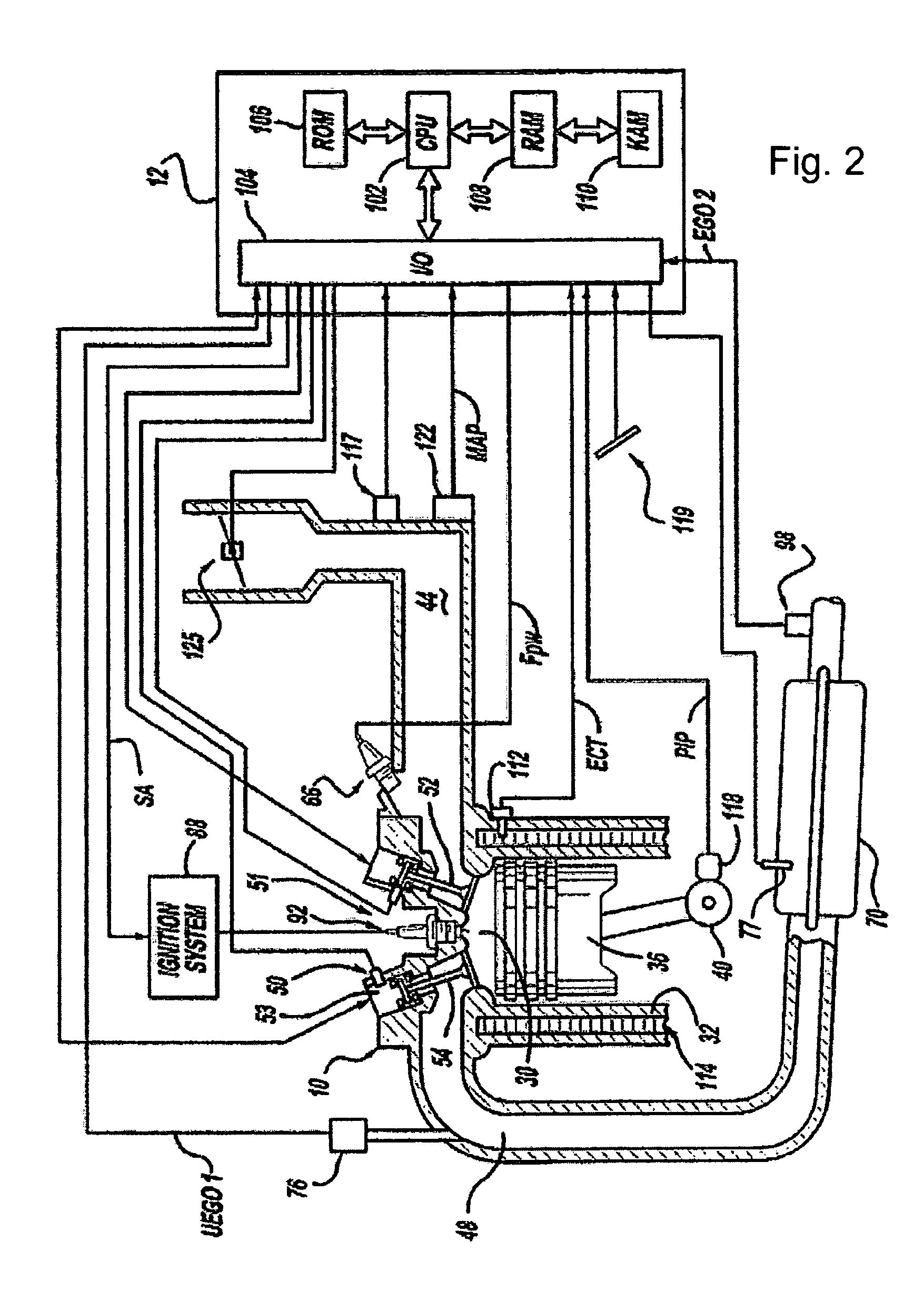
The patent describes a method and system for controlling the operation of an engine and automatic transmission in a vehicle to improve the driving experience during shifts. The system includes an engine with a valve that can be controlled to increase or decrease engine torque during certain phases of a shift. This allows for a higher bandwidth torque increase during shifts, without the need for additional devices or depleting battery storage. The system also uses the slip ratio of the torque converter to provide consistency from shift to shift. The technical effect of this patent is improved driving feel and consistency during shifts in vehicles with automatic transmissions.

Problems solved by technology

In some automatic transmissions, there may be large deviations in the transmission output torque during the torque and inertia phases of a shift event.
However, while spark retard allows engine output torque to be rapidly decreased, there can be a penalty in increased fuel consumption and emissions.
Further spark retard can generally only decrease the engine output torque from an optimal point.
However, the responsiveness of throttle modulation may be limited by the intake manifold filling dynamics lag, and the responsiveness of the ETC actuator.
However, such an approach requires a sufficiently fast actuator to control the transmission input torque, such as a crankshaft mounted SA.
While a SA can potentially be used to modulate the transmission input torque during a shift, the maximum torque capacity of a typical starter alternator may be less than half the engine torque capacity, thus limiting such an approach.
Further, the SA torque may be inversely proportional to the SA shaft speed and may also be limited by the battery state of charge.

Method used


Image

  • Driveline shift quality in variable valve engine equipped drivelines
  • Driveline shift quality in variable valve engine equipped drivelines
  • Driveline shift quality in variable valve engine equipped drivelines

Examples


example simulation

[0051 data of various portions of the above approach is shown with regard to FIGS. 5-10. In this example, The EVA engine strategy provided modes that included only 4-stroke firing cylinder operation with an option to switch between four and eight firing cylinders. However, as noted above herein, addition modes may be used, such as increased strokes, and additional numbers of active cylinders, as well as variable number of active valves on either active or inactive cylinders.

[0052]The data discussed below shows the transmission output torque response during a tip-in from idle with a first to second gear up-shift, 1-2 up-shift, at 3,500 RPM. As shown in FIGS. 5-10 an improved transmission output torque response can be achieved by providing: a positive torque gradient during the torque phase, a torque reduction during the inertia phase, and a torque increase during the final phase.

[0053]FIG. 5 shows a comparison of the above approach (solid line) to an approach using torque reduction a...


PUM


Abstract

In one example, a method for controlling powertrain operation in a vehicle is provided, the powertrain having an engine and an automatic transmission, the engine having at least an electrically actuated cylinder valve. The method includes changing gears from a first discreet gear ratio to a second discreet gear ratio of the transmission; and increasing engine torque during a torque phase of said gear change by changing operation of the electrically actuated cylinder valve, and decreasing engine torque during an inertia phase of said gear change.

Description

BACKGROUND AND SUMMARY[0001]Vehicle with automatic transmissions typically employ various approaches to control engine operation during shifting to improve drive feel. Specifically, in some cases, it can be desired to control the transmission output torque during up and / or down shifts so that a constant transmission output torque is maintained during a shift.[0002]In some automatic transmissions, there may be large deviations in the transmission output torque during the torque and inertia phases of a shift event. In one approach, variation in the transmission output torque may be controlled by calibrating the capacity and timing of the on-coming and off-going clutches and by using spark retard to decrease the engine output torque during the inertia phase. However, while spark retard allows engine output torque to be rapidly decreased, there can be a penalty in increased fuel consumption and emissions. Further spark retard can generally only decrease the engine output torque from an ...

Claims


Application Information

Patent Timeline
Patent Type & Authority Patents(United States)
IPC IPC(8): B60W10/06
CPCB60W30/19F16H63/502B60W10/06B60W10/11Y10T477/675Y10T477/67F16H61/0437
Inventor HROVAT, DAVORGIBSON, ALEXKOLMANOVSKY, ILYA V.MCCALLUM, JAMESKRASKA, MARVIN PAUL
Owner FORD GLOBAL TECH LLC
Learn More