
Z actuator with anti-gravity

a technology of anti-gravity and actuator, which is applied in the direction of photomechanical equipment, generators/motors, instruments, etc., can solve the problems of improper function, excessive vibration, and often adversely affect the performance of precision instruments, etc., and achieve the effect of facilitating operation

Inactive Publication Date: 2008-12-09
NIKON CORP
View PDF19 Cites 6 Cited by
  • Summary
  • Abstract
  • Description
  • Claims
  • Application Information

AI Technical Summary

Benefits of technology

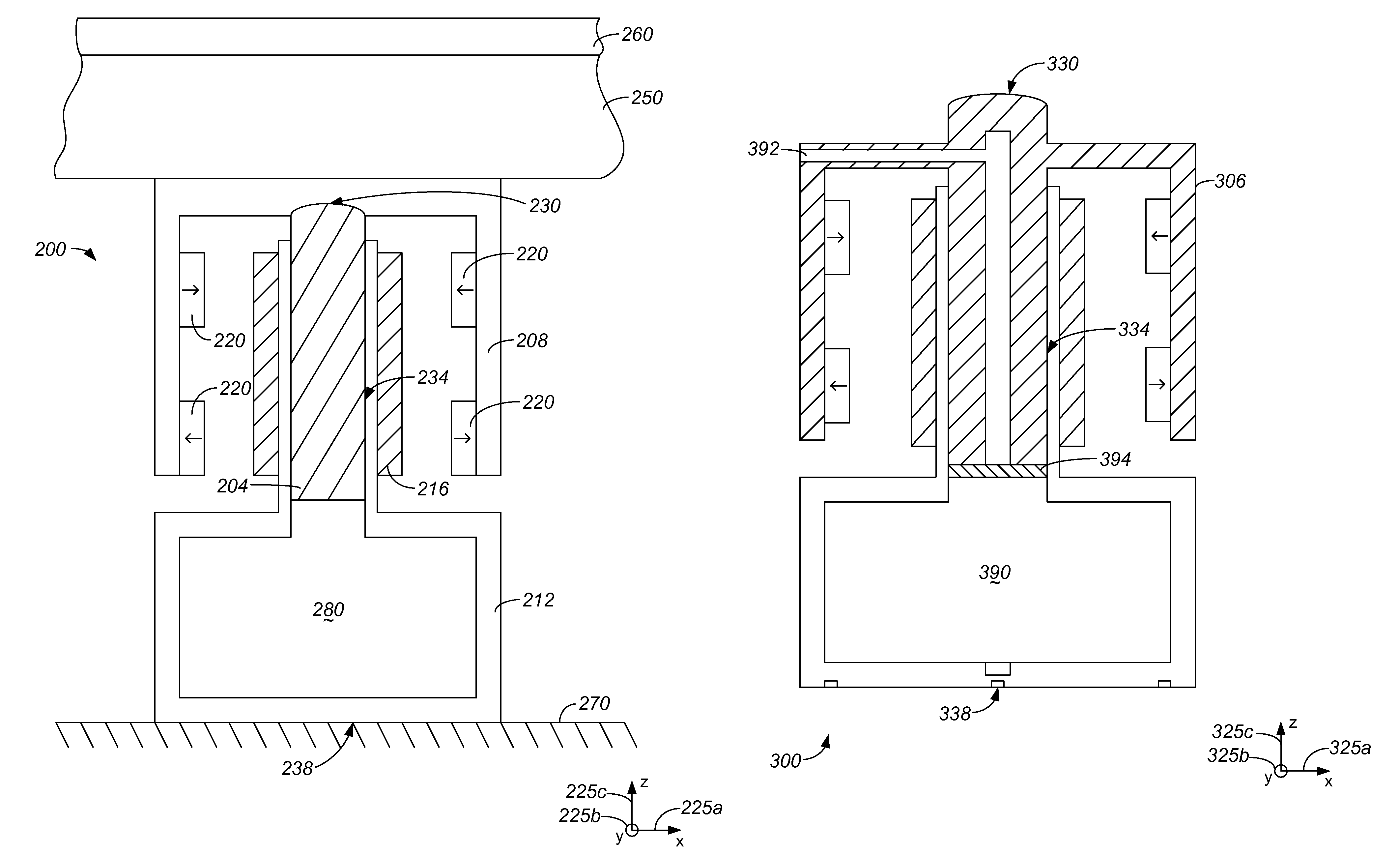
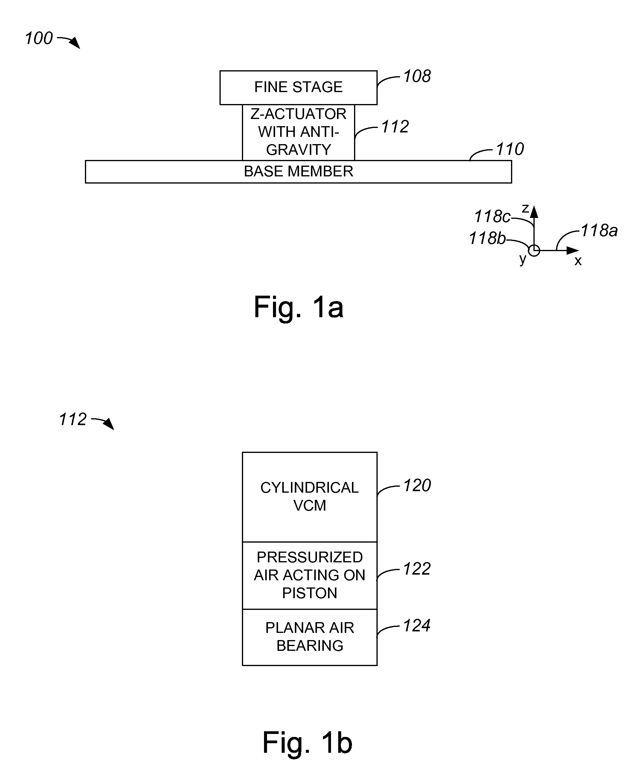
[0013]An actuator assembly which provides a force in a Z-direction while being capable of supporting weight relative to the Z-direction and providing relatively long stroke planar motion enables a stage, as for example a fine stage or a wafer table, which is actuated in the Z-direction by the actuator, allows for the stage to have up to six degrees of freedom and to have the ability to be directly driven while being able to scan in an X-direction and a Y-direction. Hence, a combination Z actuator with anti-gravity facilitates the operation of a stage with six degrees of freedom, and enables a stage to be directly driven in up to six degrees of freedom.
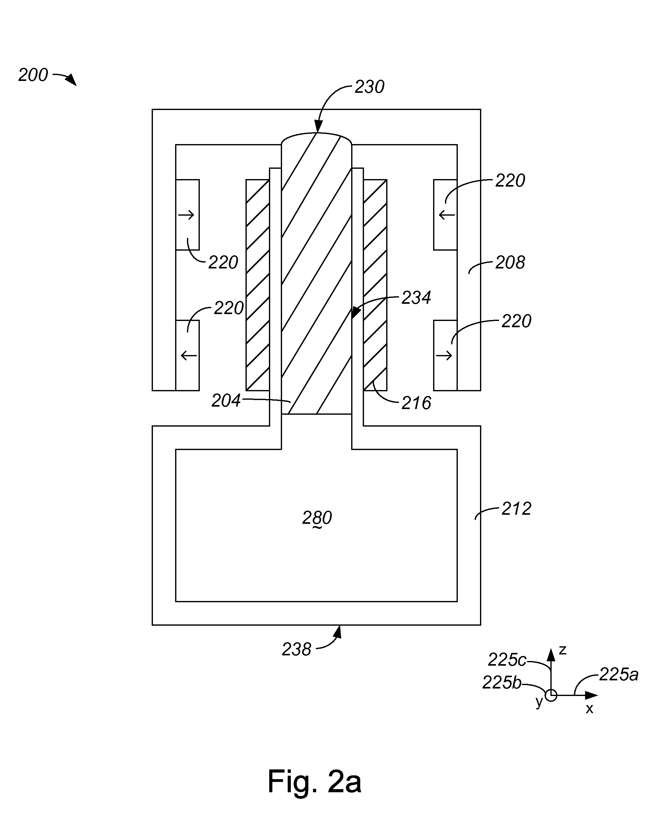
[0014]According to another aspect of the present invention, a stage device includes a fine stage, a guide surface or a base member, and an actuator assembly. The actuator assembly includes a voice coil motor and a guide bearing arrangement, as well as a yoke that is coupled to the fine stage. The actuator assembly also includes a piston arrangement that is arranged to substantially support a weight of the fine stage in a z-direction The guide bearing arrangement includes a planar air bearing that enables the actuator assembly to move over the base member in an x-direction, in a y-direction, and about the z-direction. In one embodiment, the piston arrangement includes a piston and pressurized air, and the weight of the fine stage is substantially supported in the z-direction by the piston arrangement when the piston is acted upon by the pressurized air.
[0015]In accordance with another aspect of the present invention, a stage device includes a fine stage, a base member, and an actuator assembly. The actuator assembly is arranged to contact the fine stage and includes a voice coil motor, a guide bearing arrangement, and a center pole and yoke assembly. A piston arrangement, which is also included in the actuator assembly, substantially supports a weight of the fine stage in a z-direction and the guide bearing arrangement includes a planar air bearing that enables the actuator assembly to move over the base member in an x-direction, in a y-direction, and about the z-direction. In one embodiment, the actuator assembly further includes a spherical bearing that is coupled to the center pole and yoke assembly. In such an embodiment, the spherical bearing enables the center pole and yoke assembly to rotate relative to the fine stage about the x-direction and the y-direction.

Problems solved by technology

By way of example, excessive vibration often adversely affects the performance of precision instruments.
When the performance of a precision instrument such as a wafer table is adversely affected, products formed using the precision instrument may be improperly formed and, hence, function improperly.
This relatively high stiffness in the Z-direction typically leads to relatively poor vibration transmissibility.
Poor vibration transmissibility may compromise the integrity of a wafer that undergoes an exposure process while supported on the wafer table.
Further, a flexural bearing may not be suitable for use if a wafer table is to utilize more than three degrees of freedom.
For example, a six degree of freedom wafer table would not allow for the use of a flexural bearing, since a six degree of freedom wafer table may not be constrained in a direction that is typically constrained by a flexural bearing.

Method used


Image

  • Z actuator with anti-gravity
  • Z actuator with anti-gravity
  • Z actuator with anti-gravity

Examples


Embodiment Construction

[0028]It is generally desirable for a wafer table, or a fine stage, to be able to be moved along a z-axis, as well as about an x-axis and a y-axis for focus and leveling control purposes. In other words, in order for focus and leveling control to be achieved, a wafer table typically has the ability to translate relative to a z-axis, as well as the ability to rotate relative to an x-axis and a y-axis. Additionally, to further enable focus and leveling control to be accurately achieved, a wafer table is generally supported against the force of gravity, and guided to control motion along the x-axis, along the y-axis, and about the z-axis.

[0029]An overall device which combines a Z actuator and an anti-gravity device may be used to support a wafer table against the force of gravity, while enabling motion along an x-axis and a y-axis, as well as rotational motion about a z-axis, to be guided. Such a device, when supporting a wafer table, also allows the wafer table to be moved appropriate...


PUM


Abstract

Methods and apparatus which are suitable for actuating a stage relative to a z-axis and supporting the weight of the stage against the force of gravity are disclosed. According to one aspect of the present invention, an actuator device includes a first arrangement, a magnetic system, a piston, and a guide bearing arrangement. The first arrangement includes a yoke and a center pole, and the magnetic system includes a magnet that is coupled to the yoke as well as a coil which cooperate to function as a voice coil motor. The piston supports at least a weight associated with the first arrangement, and the guide bearing arrangement includes a planar air bearing that enables the device to move over an external surface.

Description

CROSS-REFERENCE TO RELATED PATENT APPLICATION[0001]The present application claims priority to U.S. Provisional Patent Application No. 60 / 611,590, filed Sep. 21, 2004, which is incorporated herein by reference in its entirety.BACKGROUND OF THE INVENTION[0002]1. Field of Invention[0003]The present invention relates generally to semiconductor processing equipment. More particularly, the present invention relates to a method and an apparatus for enabling a Z-actuator and an anti-gravity device to be substantially combined in a single device.[0004]2. Description of the Related Art[0005]For precision instruments such as photolithography machines which are used in semiconductor processing, factors which affect the performance, e.g., accuracy, of the precision instrument generally must be dealt with and, insofar as possible, eliminated. By way of example, excessive vibration often adversely affects the performance of precision instruments. When the performance of a precision instrument such...

Claims


Application Information

Patent Timeline
Patent Type & Authority Patents(United States)
IPC IPC(8): H02K41/00H02N2/00
CPCG03F7/70758G03F7/70816H02N15/02H02K41/0354H02K2201/18
Inventor HAZELTON, ANDREW J.
Owner NIKON CORP
Learn More