

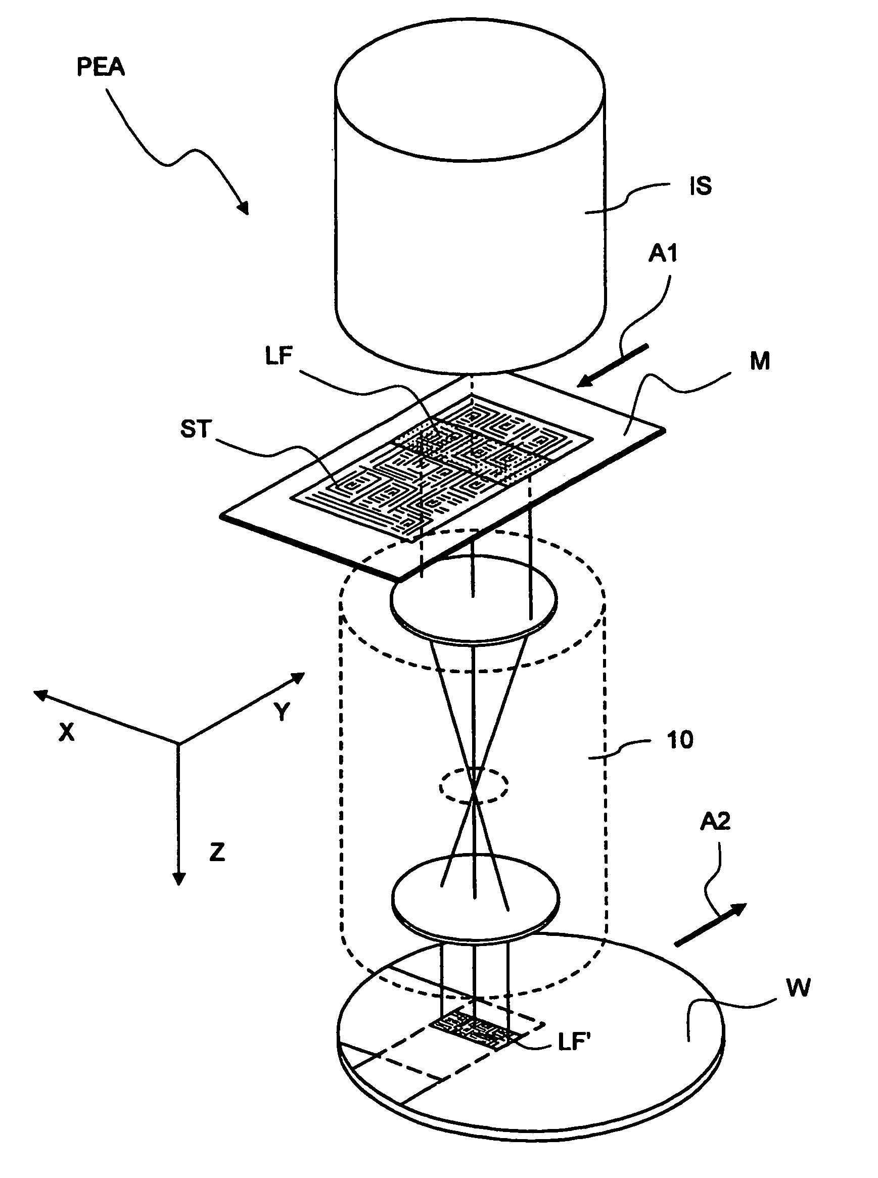
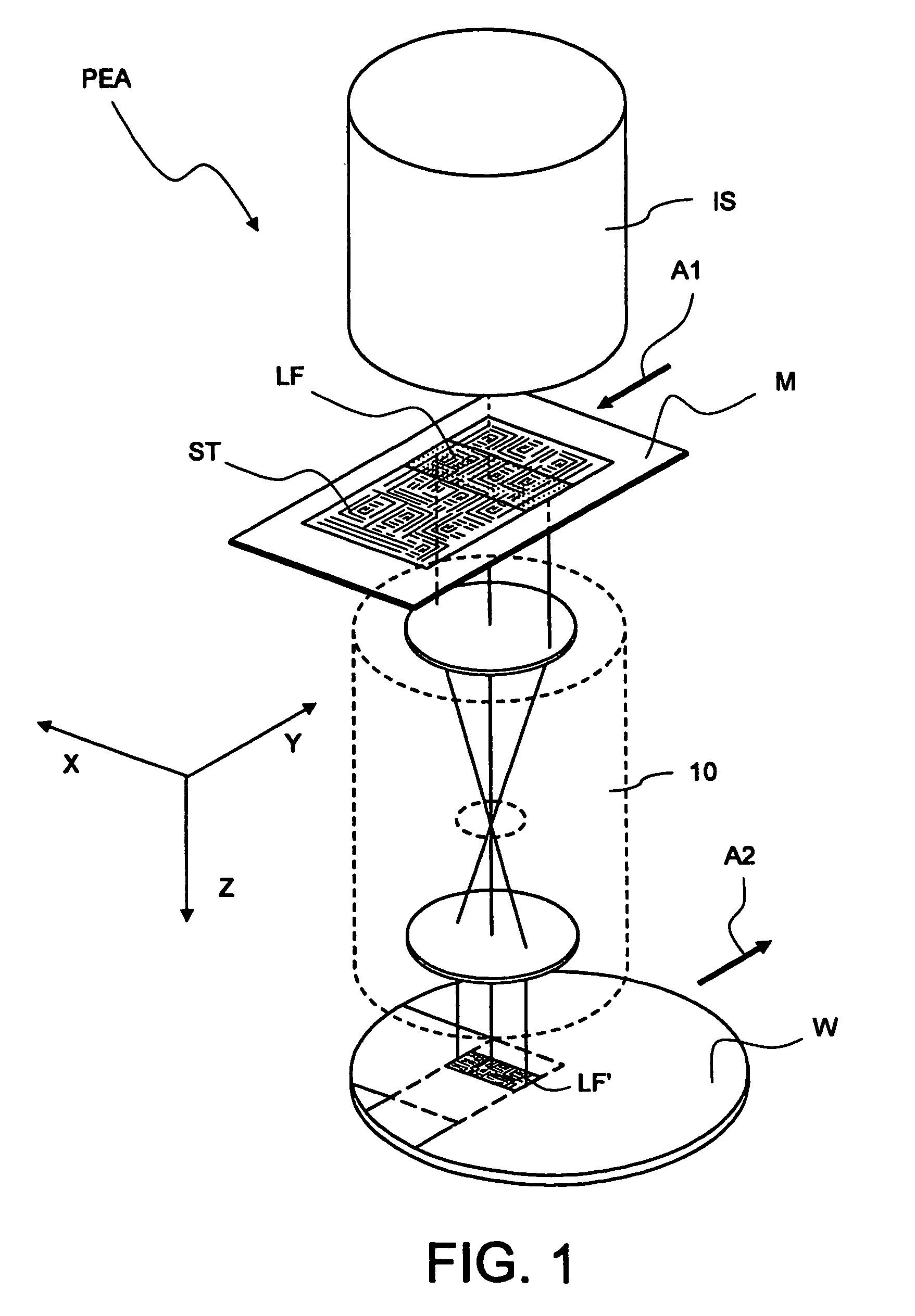
Projection exposure apparatus
a technology of projection exposure and exposure apparatus, which is applied in the direction of magnification glasses, mountings, instruments, etc., can solve the problems of increasing the heating of the lenses, reducing the brightness of the image, and the conventional lens materials such as quartz glasses are not sufficiently transparent in the deep ultraviolet wavelength domain, so as to reduce the quantity of expensive fluoride crystals and achieve the effect of optimizing the use of fluoride crystals, reducing aberrations, and reducing the quantity of expensive flu
- Summary
- Abstract
- Description
- Claims
- Application Information
AI Technical Summary
Benefits of technology
Problems solved by technology
Method used
Image

Examples
first embodiment
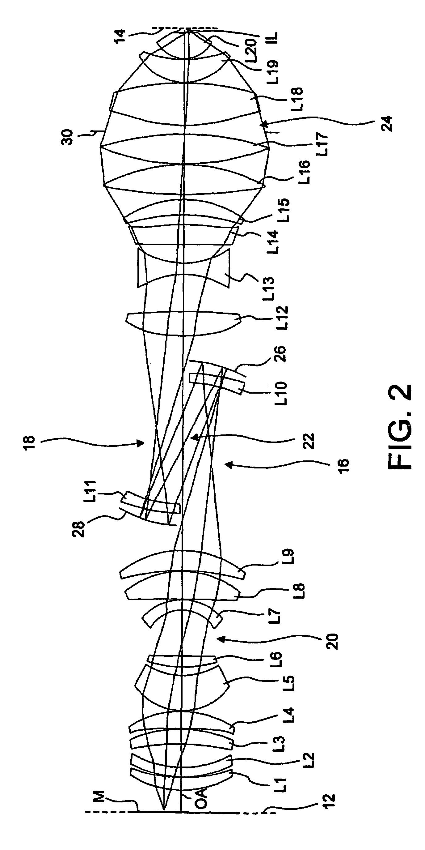
[0162]In the projection objective 10′, the threshold value for the lifetime / lens heating susceptibility factor KLT / LH has been determined to be 5. This means that all lenses with
KLT / LH>5 (13)
are significantly susceptible to deteriorations due to lifetime and / or lens heating effects and consequently should be made of a fluoride crystal such as CaF2. With this determination of the threshold value for the lifetime / lens heating susceptibility factor KLT / LH, a fluoride crystal, here CaF2, should be selected according to step S7 only for the last lens L20′.
[0163]The lens L20′ has a very large geometrical birefringence factor KgIB of more than 52.4 and thus causes significant birefringence. Therefore it is necessary to compensate for the birefringence caused by the lens L20′.
[0164]The most promising approach to compensate this birefringence is to split up the lens L20′ into two lens parts rotated around the optical axis. If a (100) crystal material is selected, a relative rotation by 45° ...
second embodiment
[0167]In the projection objective 10′, the threshold value for the lifetime / lens heating susceptibility factor KLT / LH has been determined to be 1.8. This means that all lenses with
KLT / LH>1.8 (13)
are significantly susceptible to deterioration due to lifetime and / or lens heating effects and consequently should be made of a fluoride crystal such as CaF2. With this determination of the threshold value for the lifetime / lens heating susceptibility factor KLT / LH, a fluoride crystal, here CaF2, should be selected according to step S7 not only for the last lens L20′, but also for the lenses L10′ and L19′.
[0168]Since these lenses L10′ and L19′ are now, compared with the first embodiment shown in FIG. 10, made of a material having a different index of refraction, the design of the projection objective 10′ has to be slightly adjusted. Tables 7 and 8 contain the adjusted design specification of the projection objective 10′.
[0169]The most promising approach to compensate this birefringence is to...
third embodiment
[0171]In the projection objective 10′, the threshold value for the lifetime / lens heating susceptibility factor KLT / LH is still 1.8 so that the last lens L20′ and the lenses L10′ and L19′ are made of a fluoride crystal material.
[0172]However, if the compensation achieved with three lenses L10′, L19′ and L20′ is considered to be insufficient (step S10-1), it may be envisioned to improve the compensation by selecting a fluoride crystal for an additional lens. L14′ is a good candidate for this selection because according to table 6, the lens L14′ has, in spite of its small lifetime / lens heating susceptibility factor KLT / LH of 0.8, a large geometrical birefringence factor KgIB=17.0 (see step S10-3).
[0173]A fourth lens made of a fluoride crystal material makes it possible to choose different compensation approaches. For example, the last two lenses L19′ and L20′ may be made of (111) crystals with their crystal lattices rotated around the optical axis by an angle of 60° or an uneven multip...
PUM
 Abstract
Description
Claims
Application Information