
Fly fishing reel

a technology of flying fishing and reels, applied in the field of flying fishing reels, can solve the problems of increasing the frequency of lurching action, and achieve the effect of simplifying the design

Inactive Publication Date: 2008-12-16
BAWER TECH
View PDF13 Cites 7 Cited by
  • Summary
  • Abstract
  • Description
  • Claims
  • Application Information

AI Technical Summary

Benefits of technology

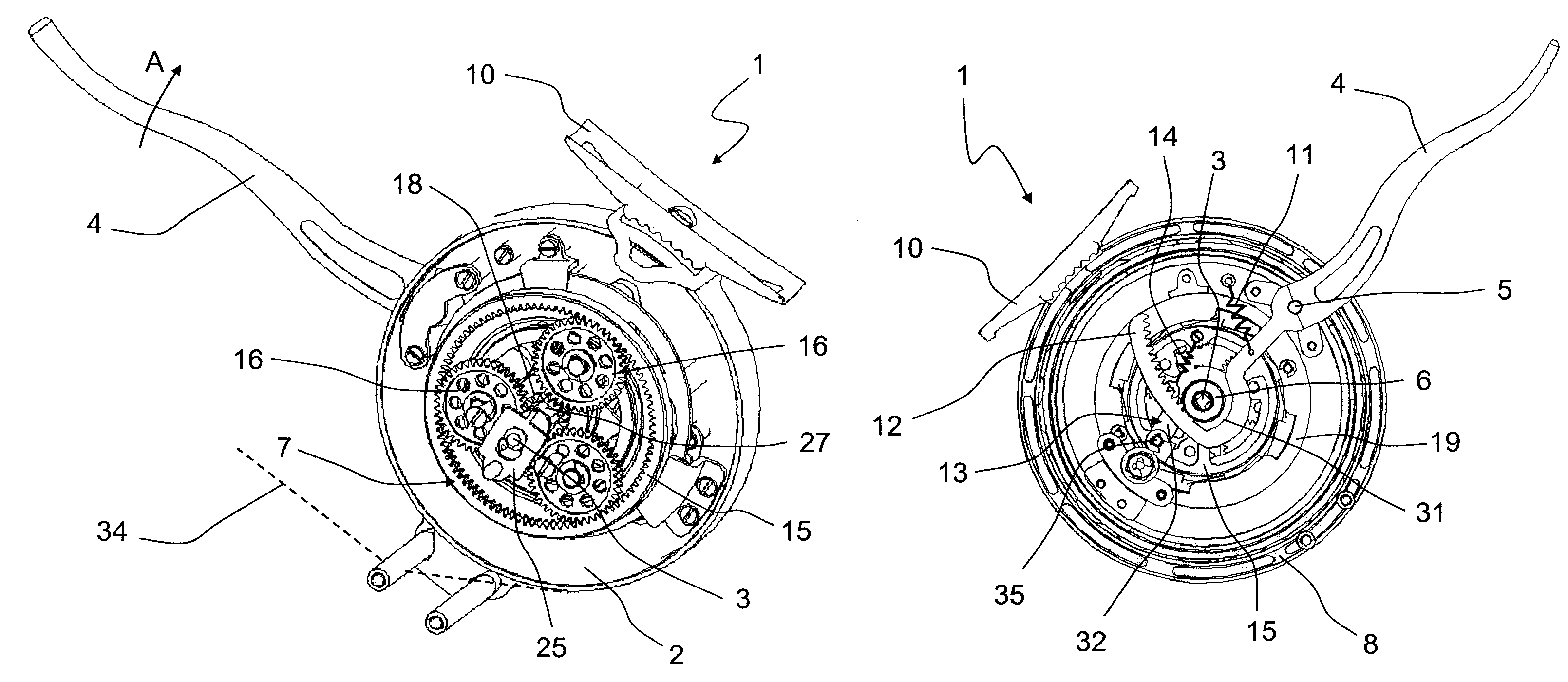
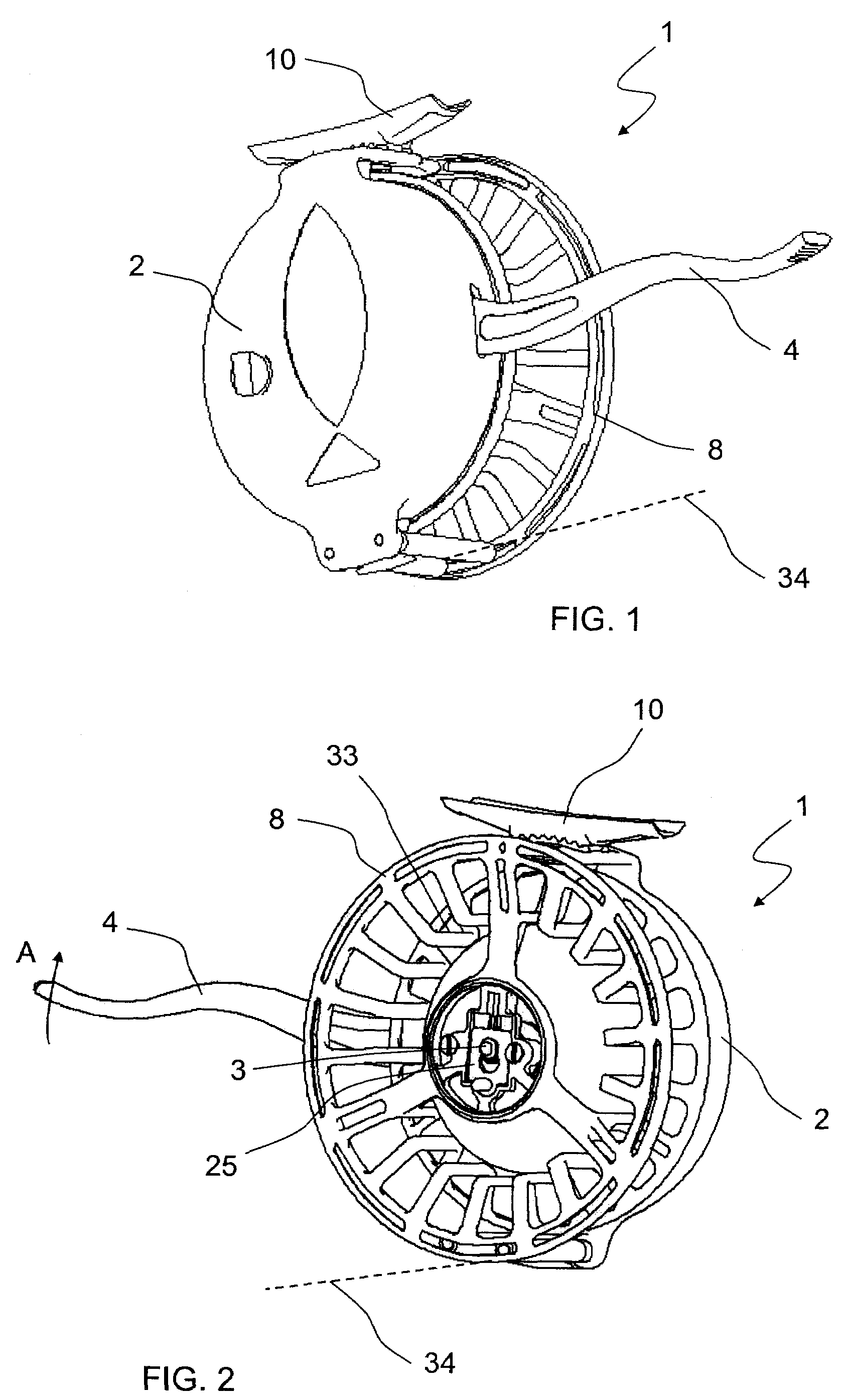
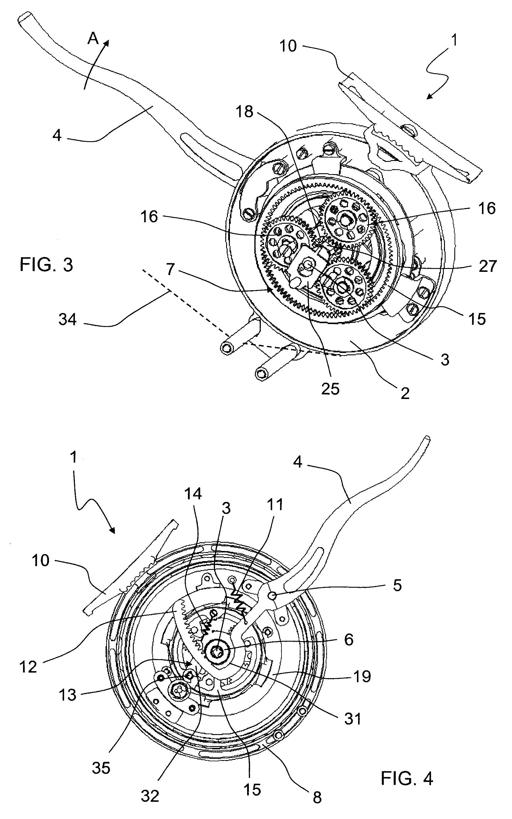
"The invention is a fly fishing reel that aims to improve the two main factors that affect fishing success: lurching of the rod and slow retrieval speed. The reel features a gearing system with a planetary train and a driving lever that activates the gearing. The planetary train has a high gearing ratio, which allows for continuous adjustment of the brake tension to prevent uncontrolled line feed-out. The reel is designed to retrieve the line with the least tension variation, reducing lurching action and tension variations in the line. The driving lever is concentric with the main axis, and the secondary axis is parallel to the main axis, with a driving lever swivelling around the secondary axis. The reel also includes a secondary axis parallel to the main axis, with a driving lever swivelling around the secondary axis. The planetary train has a good gearing / occupied volume ratio, which means the reel can take in a greater length of line each time the lever is activated. The driving lever is concentric with the main axis, and the brake is adjustable to the lowest level possible to prevent uncontrolled line feed-out. The invention solves the problem of slow retrieval speed and unstable line tension in semi-automatic reels."

Problems solved by technology

With semi-automatic reels, although the line tension is much more constant than when retrieving by hand, the gearing ratio is not high enough, and so the driving lever has to be activated several times in order to bring the fish closer quickly enough, which also increases the frequency of the lurching action.
In practice, this leads to users tending to retrieve the line by hand with the problem this implies, as described above.

Method used


Image

  • Fly fishing reel
  • Fly fishing reel
  • Fly fishing reel

Examples


second embodiment

[0067]FIGS. 9 to 16 show the reel. FIGS. 14, 15 and 16 show sections along the lines A-A, B-B and C-C of FIG. 10 respectively. As can be seen particularly clearly in the section shown in FIG. 15, brake 109 of reel 101 comprises a first ring 135 and a second ring 136. First ring 135 has a first conical outer surface 137 that cooperates with second conical inner surface 138 of second ring 136 to produce the corresponding braking torque.

[0068]Also, second ring 136 has a fifth pinion 143 that meshes with a fourth pinion 141 that is part of free wheel mechanism 120. Free wheel mechanism 120 also comprises a one-way bearing 142 with a third pinion 140 which, in turn, meshes with a first outer gear teeth 139 provided on ring gear 115 of gearing 107.

[0069]In this embodiment, the force of the brake is regulated by regulating means 122. Cap 144 has a positive locking with first ring 135 in the form of a hexagonal screw. First ring 135 has an outer thread 145 which, as can be seen in detail in...

third embodiment

[0073]FIGS. 17 to 22 show the reel. Brake 209 comprises a brake disc 219 in the form of a ring mounted floating, externally and concentrically on an outer blocking diameter 250 of ring gear 215. Brake disc 219 is caused to brake by two brake blocks 221a, 221b. In this embodiment the second break block 221b can be moved in the direction perpendicular to the second surface 251b of brake disc 219 by means 222 for regulating the force of brake 219. In particular said regulating means 222 are made up of a take-up screw 224 that compresses a take-up spring 223. When compressed, take-up spring 223 pushes against second movable break block 221b. This embodiment is particularly robust, because the small parts that move are the minimum essential parts. However, it would be feasible for both brake blocks 221a and 221b to be able to move with respect to disc 219, whereas disc 219 would be mounted fixedly in the direction of main axis 203 on outer blocking diameter 250 of ring gear 215.

[0074]As ...


PUM


Abstract

Fly fishing reel. The reel comprises a housing (2, 102, 202), a main axis (3, 103, 203), a swivel driving lever (4, 104, 204) preloaded by elastic recovery means (11, 111, 211) and a first pinion (6, 106, 206) driven by driving lever (4, 104, 204). First pinion (6, 106, 206) is coaxial to main axis (3, 103, 203). The reel also comprises a reel (8, 108, 208) for winding up line (34, 134, 234) that is coaxial to main axis (3, 103, 203) and a brake (9, 109, 209) for spool (8, 108, 208). Between first pinion (6, 106, 206) and spool (8, 108, 208) a gearing (7, 107, 207) is provided. Said gearing (7, 107, 207) comprises at least one planetary train made up of a second pinion (18, 118, 218), at least three planet gears (16, 116, 216) and a ring gear (15, 115, 215). Ring gear (15, 115, 215) is linked to first pinion (6, 106, 206) via a one-way clutch (13, 113, 213).

Description

FIELD OF THE INVENTION[0001]The invention relates to a fly fishing reel comprising a housing, a main axis, a swivel driving lever, elastic recovery means for the lever rest position, a first pinion driven by the driving lever, said first pinion being provided coaxially to the main axis, a line wind up spool, provided coaxially to the main axis and a spool brake.STATE OF THE ART[0002]In the state of the art, manual, semi-automatic and automatic fly fishing reels are known.[0003]The manual reel consists of a spool that can wind up the line mounted on an axis provided with in housing that is attached to the rod. The spool has a handle that allows it to be activated in a circular movement around the axis in the housing in order to retrieve the line. This type of reel does not have a gearing, whereby line retrieval is relatively slow.[0004]It is worth mentioning that in fly fishing, the line is not simply a fishing line wound on the reel. It has at least two parts. At the end of the bait...

Claims


Application Information

Patent Timeline
Patent Type & Authority Patents(United States)
IPC IPC(8): A01K89/01
CPCA01K89/016A01K89/033A01K89/05
Inventor BAO-COUTADO, CARLOS
Owner BAWER TECH
Learn More