Al technical title is built by PatSnap Al team. It summarizes the technical point description of the patent document.
a technology of carbon fiber and fork, which is applied in the direction of friction roller based transmission, steering device, cycle equipment, etc., to achieve the effect of less strength reduction and adding to overall fork strength
Active Publication Date: 2008-12-16
TREK BICYCLE CORPORATION
View PDF20 Cites 13 Cited by
Summary
Abstract
Description
Claims
Application Information
AI Technical Summary
This helps you quickly interpret patents by identifying the three key elements:
Problems solved by technology
Method used
Benefits of technology
[0009]A bonded steer tube enables the use of a multiplicity of materials such as the preferred aluminum, steel, titanium, or carbon fiber reinforced plastic. Beveling or tapering the fiber reinforced plastic shell and the steer tube enables a gradual transition zone of carbon crown and legs to the metal steer tube. This allows for a smooth stress transition zone from the crown region to the steer tube.
[0010]Molding the shell for the fork enables precise forming of the crown race to size. No post machining is required which therefore allows for continuous fibers at the highest stress areas. Bonded on the fork is also a crown race load dispersion ring
[0015]The aluminum steer tube extension receives a star-fangled nut of a typical threadless headset. The use of aluminum or other metal is advantageous in a threadless configuration because it suffers less from strength reduction as a result of the embedding of the star-fangled nut teeth in the interior wall, when compared to a fiber reinforced plastic composite material. The use of high modulus composite material extending continuously into the steer tube adds to overall fork strength
Problems solved by technology
In each approach to a composite fork, separate metal dropouts are used for wheel attachment, primarily because of wear considerations as damage to a plastic composite resulting from wheel attachment can compromise strength.
Method used
Image
Click on the blue label to locate the original text in one second.
Reading with bidirectional positioning of images and text.
Examples
Embodiment Construction
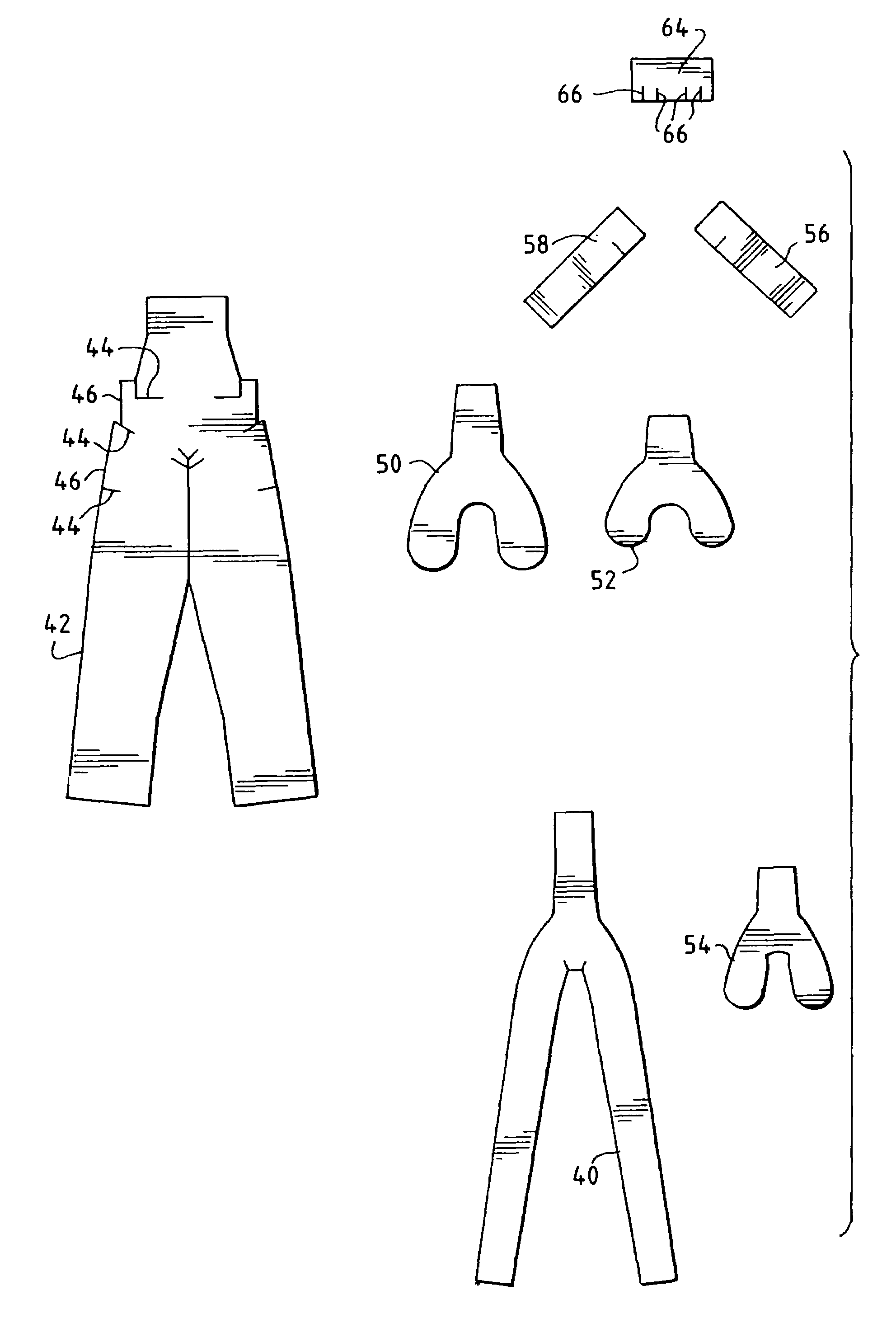
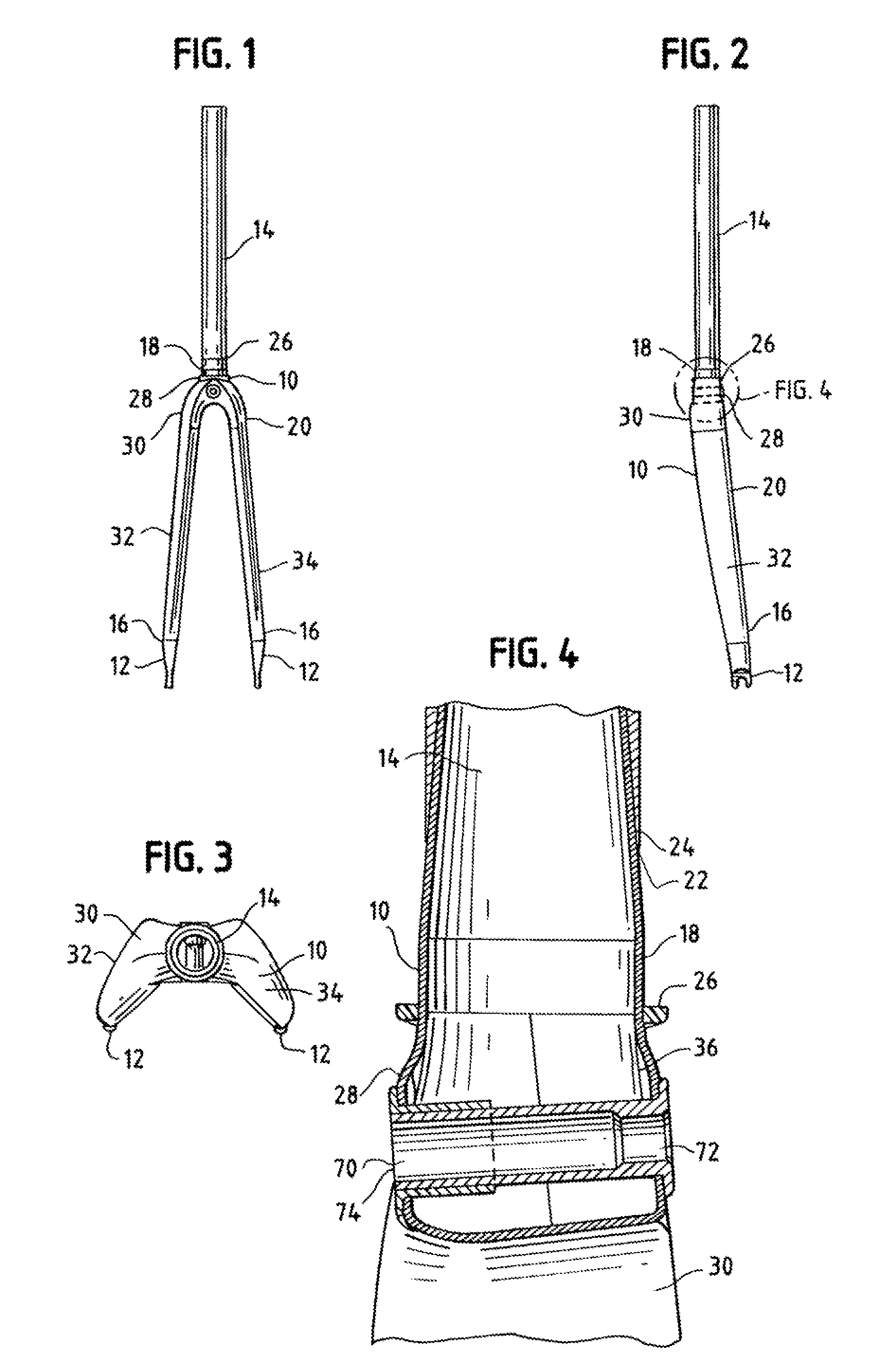
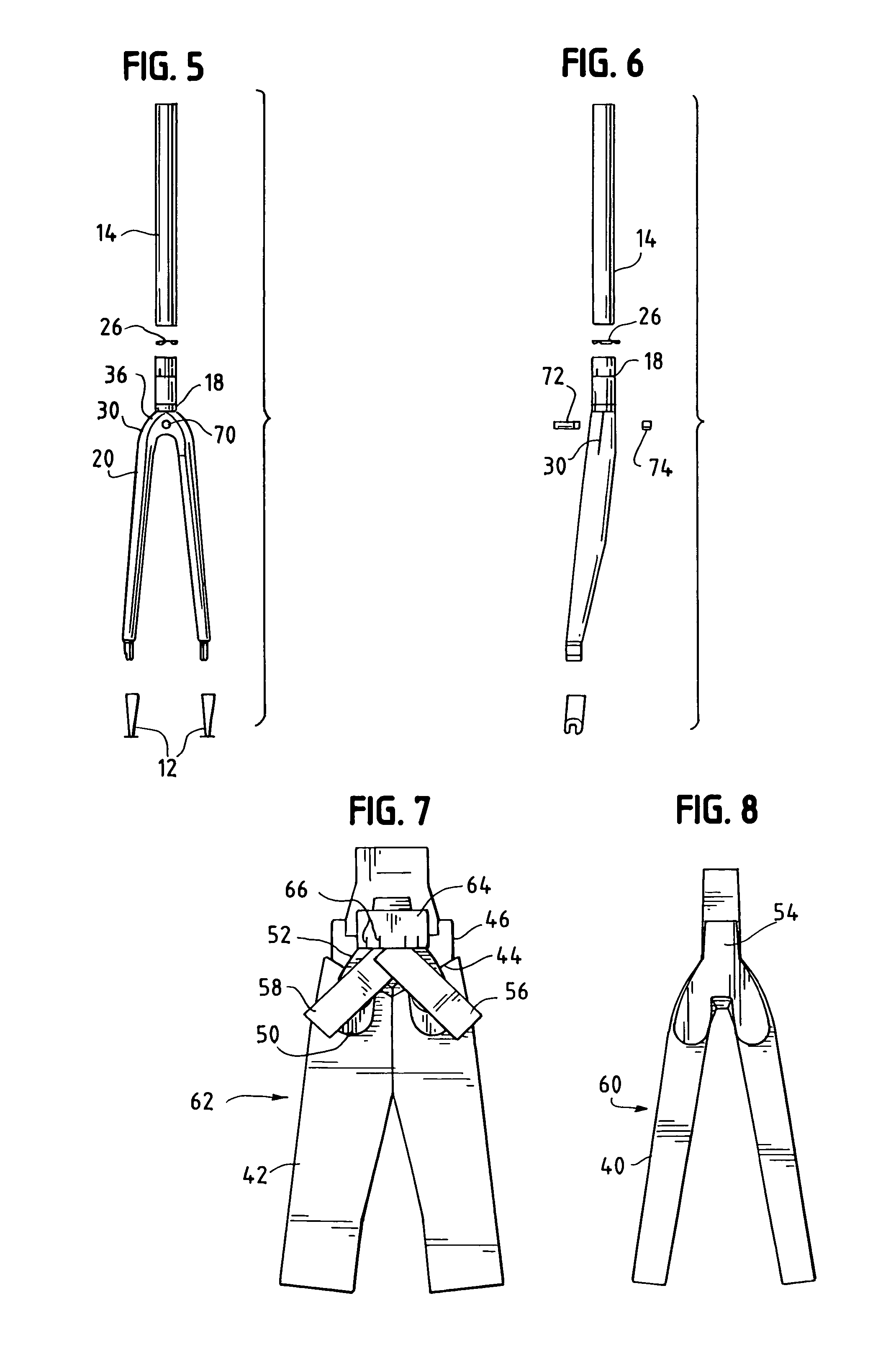
[0025]The invention uses optimum compaction, low void molding, consistent with the teachings of Nelson U.S. Pat. No. 6,270,104 B1, of a completely hollow bicycle fork 10 with comolded dropouts 12 and a bonded steer tube 14. Continuous fibers in the fork extend from the tip 16 to steer tube base 18. The fiber reinforced plastic structure extending in this manner is referred to as the shell 20. Tube 14 is formed with a beveled bottom edge 22 which mates with a corresponding beveled top edge 24 of base 18. Beveled edges 22, 24 provide a gradual transition zone for the fiber reinforced plastic to metal joint thereby providing superior durability and predictability in strength properties as well as avoiding abrupt joints that result in stress concentrations. While aluminum is preferred for tube 14, other materials could be used such as steel or titanium. Additionally, should a carbon fiber tube be determined to be acceptable, a machine made tube using wound fibers could be economically b...
PUM
Abstract
A continuous fiber reinforced plastic bicycle fork has continuous fibers extending from the tip of the fork blades to the steer tube, formed through optimum compaction, low void molding resulting in precise forming of the fork shell such that a metal steer tube, metal bearing races, metal dropouts and metal brake mount are used to attach metal components such as a headset and star-fangled nut, handlebar stem, wheel and brake thereby eliminating metal component to carbon fiber contact to preserve the integrity of the fiber reinforcements and plastic matrix.
Description
CLAIM FOR PRIORITY[0001]Applicant's claim priority of U.S. Provisional Application No. 60 / 483,665 filed Jun. 30, 2003.BACKGROUND OF THE INVENTION[0002]1. Field of the Invention[0003]The invention is a continuous fiber carbon fork for a bicycle and a method of manufacturing a continuous fiber carbon fork using optimum compaction, low void molding of fiber reinforced plastic to form a fork having laminations from tip to steer tube which have continuous fibers.[0004]2. Description of Related Art[0005]Notable in composite bicycle frame patents is the fact that the disclosures in the leading patents focus on the frame itself, to the exclusion of the fork. Thus, Nelson U.S. Pat. No. 6,270,104 B1, Duplessis U.S. Pat. No. 5,076,601, Trimble U.S. Pat. No. 5,158,733, Brezina U.S. Pat. No. 4,493,749 and Derujinsky U.S. Pat. No. 4,900,048 do not show forks, while Trimble U.S. Pat. Nos. 4,923,203 and 4,982,975 show forks, but only as part of the environment.[0006]An example of a threadless fork ...
Claims
Application Information
Patent Timeline
Application Date:The date an application was filed.
Publication Date:The date a patent or application was officially published.
First Publication Date:The earliest publication date of a patent with the same application number.
Issue Date:Publication date of the patent grant document.
PCT Entry Date:The Entry date of PCT National Phase.
Estimated Expiry Date:The statutory expiry date of a patent right according to the Patent Law, and it is the longest term of protection that the patent right can achieve without the termination of the patent right due to other reasons(Term extension factor has been taken into account ).
Invalid Date:Actual expiry date is based on effective date or publication date of legal transaction data of invalid patent.
Patent Type & Authority Patents(United States)
IPC IPC(8): B62K21/02B62K19/16B62K25/00
CPCB62K19/16B62K25/00
Inventor SCHUMAN, BRIAN E.CUSACK, DOUGLAS A.MADHAVAN, SRIDHARANCOLEGROVE, JAMES