Phase interpolation circuit

a phase interpolation and circuit technology, applied in pulse generators, pulse manipulation, pulse techniques, etc., can solve the problems of phase noise, longer lock time, and longer lock tim

Inactive Publication Date: 2008-12-16
REALTEK SEMICON CORP
View PDF7 Cites 29 Cited by
  • Summary
  • Abstract
  • Description
  • Claims
  • Application Information

AI Technical Summary

Benefits of technology

[0013]It is one of the object of the present invention is to provide a phase-interpolation circuit which can avoid short-circuit current and generate linearly distributed phase-interpolation signals.

Problems solved by technology

However, several disadvantages exist when the phase-lock loop circuit is used for recovering the clock-pulse, including: (a) Longer lock time.
As a result, longer lock-time is required.
The result above is the phase noise.
Because the rising and falling edges of the signal do not vary when a long and same logical signal inputs, the phase detector won't work.
Under such condition, the phase-lock loop circuit is unable to maintain the phase-lock state and the frequency will start to drift, and, as a result, the phase noise is generated in the frequency spectrum.
However, it also incurs the drawbacks of requiring lots of delay units for covering 360 degrees of clock-pulse phases, higher cost, fewer applications available, more electric power decay, and inevitable noise disturbance occurred from electrical power lines.
However, one of the difficulties is to avoid the problem of the multiphase oscillator model.
The cost and the decaying power will balance in the design.
The result above will limit the application of the data-recovery system of the multi-receiving channel described above.
The disadvantages of the phase-interpolation method in the type of conventional full swing signal type include: (a) The decaying power of the short-circuit current is large.
The disadvantage of large decaying power in the circuit exists.
However, such kind of method can only improve the linearity of the distribution of the phase by means of the ratio of current (e.g., W and 1-W shown in FIG. 1D), which is difficult to be controlled concisely.
This method cannot achieve the yield of the mass production and cannot maintain the duty cycle of the original clock-pulse.
However, it also incurs the drawback of being only able to produce the interpolation phase for the falling edge of the clock pulse, but cannot provide the interpolation phase for both the rising and falling edges of the clock pulse (as which shown in FIG. 2B).
Therefore, such kind of circuit can only be used for doubling the frequency of multiphase clock pulse.
And it will not produce a new middle phase for the doubled frequency.

Method used


Image

  • Phase interpolation circuit
  • Phase interpolation circuit
  • Phase interpolation circuit

Examples


Embodiment Construction

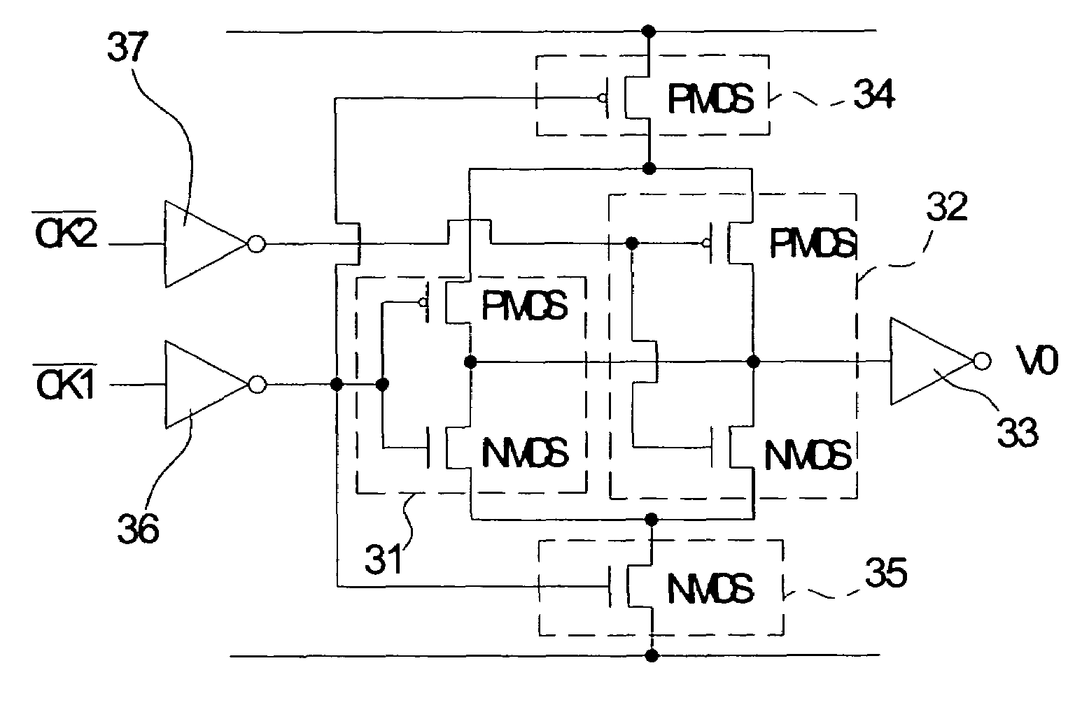
[0028]Please refer to FIG. 3, which is a schematic diagram of a preferred embodiment of the phase-interpolation circuit of the present invention. The phase-interpolation circuit shown in FIG. 3 includes five inverters and two controlled switches. The input end 311 of the first inverter 31 receives a phase-leading clock signal CK1. And the input end 321 of the second inverter 32 receives a phase-following clock signal CK2. And the output end 322 of the second inverter 32 is connected to the output end 312 of the first inverter 31 to form a common output end 30. The input end 331 of the third inverter 33 connects to the common output end 30 electrically. The output ends of the fourth inverter 36 and the fifth inverter 37 are connected to the input ends of the first inverter 31 and the second inverter 32 respectively.

[0029]The circuit further includes the first controlled switch 34 and the second controlled switch 35 to avoid short-circuit current in the present invention. The first co...


PUM


Abstract

The invention relates to a phase-interpolation circuit and a phase-interpolation signal generating circuit applying the phase-interpolation circuit. The phase-interpolation circuit can avoid short-circuit current effectively. In addition, an inter-phase signal can be interpolated between the rising edge and the falling edge of the clock pulse. The phase-interpolation signal generating device can generate multiphase clock signals which not only have linearly distributed phases but also maintain good 50% duty cycle of the multiphase clock signals.

Description

CROSS REFERENCE TO RELATED APPLICATIONS[0001]This is a continuation-in-part of application Ser. No. 10 / 079,866 filed on Feb. 21, 2002, now U.S. Pat. No. 6,727,741, entitled “A Phase-Interpolation Circuit and A Phase-Interpolation Signal Generating Device Applying the Same” and assigned to the same assignee, the contents of which are incorporated herein by reference.BACKGROUND OF THE INVENTION[0002](1) Field of the Invention[0003]The present invention relates to a phase-interpolation circuit, more particularly, a phase-interpolation circuit which can avoid short-circuit current and generate linearly distributed phase-interpolation signals.[0004](2) Description of the Prior Arts[0005]Multiphase systems are widely applied in the data-recovery systems and the phase-lock loop circuits. The multiphase systems are also a main trend of design in the communication systems nowadays.[0006]In a conventional data recovery system, after applying the equalizer to recover high frequency decayed sig...

Claims


Application Information

Patent Timeline
Patent Type & Authority Patents(United States)
IPC IPC(8): H03H11/16H03K5/00H03K5/08H03K5/13
CPCH03K5/088H03K5/13H03K2005/00286
Inventor HUANG, CHEN-CHIHCHIU, PAO-CHENG
Owner REALTEK SEMICON CORP
Why Eureka
Try Eureka