Load allocation when executing image processing using parallel processing

a technology of image processing and load allocation, applied in the field of parallel image processing, can solve the problems of reducing the possibility of processing efficiency drop, and achieve the effects of finely equalizing the variance of loads, reducing load differences, and reducing load differences

Inactive Publication Date: 2008-12-16
SEIKO EPSON CORP
View PDF10 Cites 7 Cited by
  • Summary
  • Abstract
  • Description
  • Claims
  • Application Information

AI Technical Summary

Benefits of technology

[0009]By using this embodiment, at least when starting processing of a process segment set, it is possible to process both of the first-type and second-type unit process segments in parallel using M processing units. As a result, the possibility of processing efficiency dropping can be reduced which may be caused by over concentration of the load on a specific element within the device for executing processing and having the element be a bottleneck of the processing capability. That is, it is possible to execute processing efficiently when executing image processing using parallel processing.
[0014]With this kind of aspect, using accurately estimated loads based on the immediately prior execution results, it is possible to reduce the load difference between the processing units. At the same time, it is possible to allocate unit process segments to each of the processing units so as to make it likely for the first-type and the second-type unit process segments to be parallel processed.
[0015]When allocating unit process segments to the processing unit, it is possible to perform processing like that described below. (i) One unit process segment is selected from among unit process segments which are not yet allocated to one of the processing units in the next process segment set according to a priority sequence of decreasing estimated loads. (ii) The selected unit process segment is allocated to a processing unit having a lowest total estimated load of already allocated unit process segments among the M processing units. (iii) The operations (i) and (ii) are executed repeatedly. When executing unit process segments, it is possible to perform processing like that described below. A plurality of allocated second-type unit process segments are executed continuously prior to allocated first-type unit process segment on at least one of the M processing units. A plurality of allocated first-type unit process segments are executed continuously prior to allocated second-type unit process segment on at least one of the other processing units of the M processing units. With this type of aspect as well, based on an accurately estimated load, it is possible to reduce the load difference between the processing units, and at the same time, it is possible to allocate unit process segments to each processing unit so as to make it likely for the first-type and the second-type unit process segments to be parallel processed.
[0016]Note that it is preferable to classify the N unit process segments into (a) unit process segments that are subject to unit process segment allocation according to the aforementioned priority sequence and (b) unit process segments for load balancing that are not subject to the unit process segment allocation according to the aforementioned priority sequence and the estimated loads are lower than that of the unit process segments subject to the unit process segment allocation. After the unit process segment allocation according to the priority sequence, the unit process segments that were not subject to the unit process segment allocation are allocated to a processing unit having a lowest total estimated load of already allocated unit process segments. With this kind of aspect, it is possible to more finely equalize the variance of the loads between processing units using a unit process segment for which the estimated load is small.
[0019]According to a priority sequence of decreasing estimated loads, one unit process segment may be selected from among unit process segments which are not yet allocated to one of the processing units in the next process segment set. Then the selected unit process segment may be allocated to a processing unit for which unit process segments to be processed first run out among the M processing units, and may be executed on the processing unit. With this kind of aspect, it is possible to reduce the load difference between the processing units. As a result, it is possible to process segment sets in a short time.
[0020]It is preferable to classify the N unit process segments into (a) unit process segments that are subject to unit process segment allocation according to the aforementioned priority sequence and (b) unit process segments for load balancing that are not subject to the unit process segment allocation according to the aforementioned priority sequence and their estimated loads are lower than that of the unit process segments subject to the unit process segment allocation. When allocating unit process segments to the processing unit, it is preferable to perform the operation described below. After the unit process segment allocation according to the priority sequence, the unit process segments that were not subject to the unit process segment allocation are allocated to a processing unit for which unit process segments to be processed first run out, and are executed on the processing unit. With this aspect, it is possible to perform load balancing of the processing units at a finer level.

Problems solved by technology

As a result, the possibility of processing efficiency dropping can be reduced which may be caused by over concentration of the load on a specific element within the device for executing processing and having the element be a bottleneck of the processing capability.

Method used


Image

  • Load allocation when executing image processing using parallel processing
  • Load allocation when executing image processing using parallel processing
  • Load allocation when executing image processing using parallel processing

Examples


first embodiment

B. First Embodiment

B1. Overall Constitution of the Device

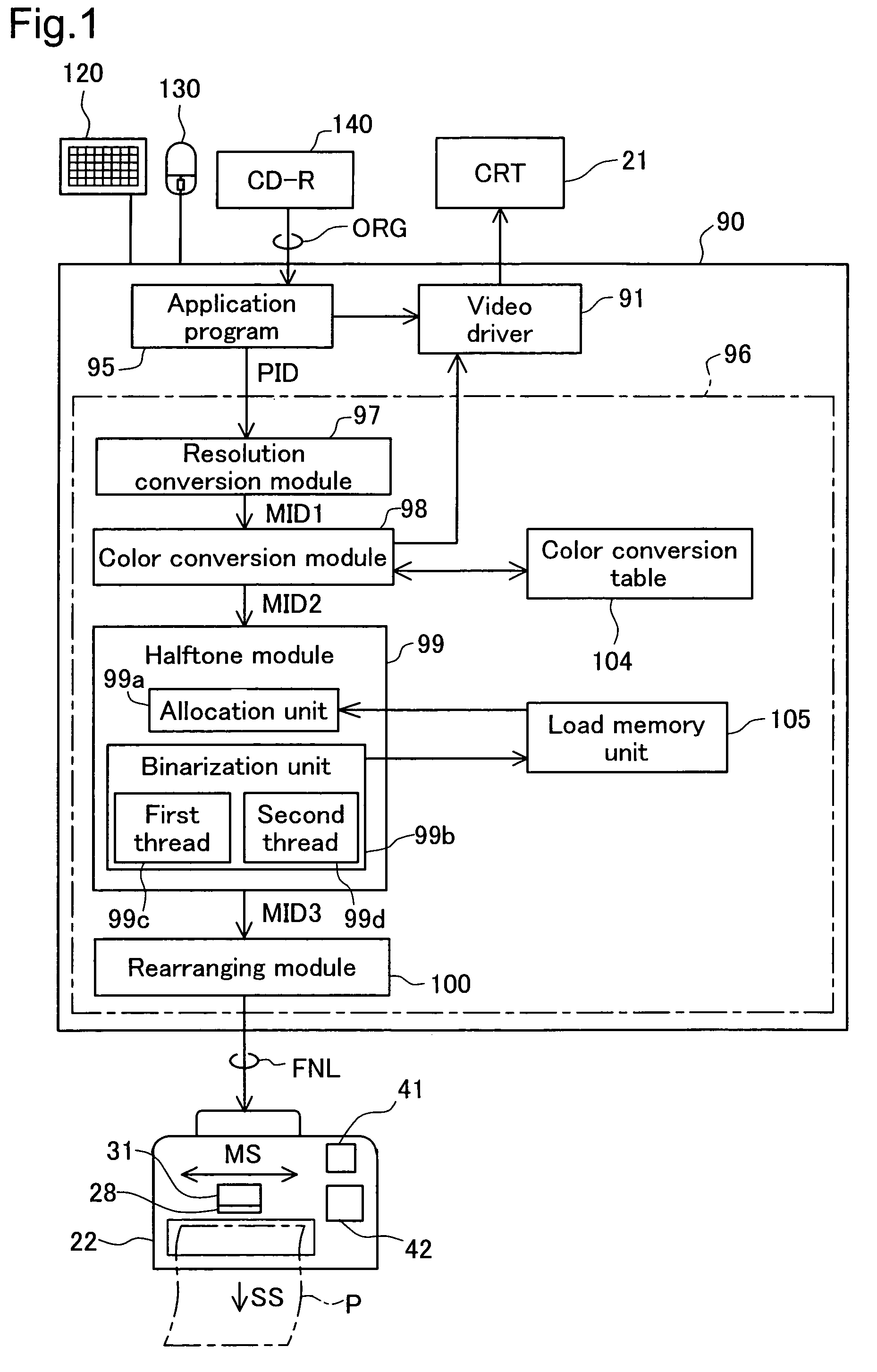
[0044]FIG. 1 is a block diagram showing the software configuration of the printing system of the first embodiment. With a computer 90, an application program 95 operates under a specified operating system. Also, a video driver 91 and the printer driver 96 are incorporated in the operating system.

[0045]The application program 95 reads original image data ORG consisting of the three color components red (R), green (G), and blue (B) from a CD-R 140, according to user instructions input from a mouse 130 or a keyboard 120. Then, processing such as image retouching is performed on the original image data ORG according to the user instructions. The application program 95 displays processed images on the CRT display 21 via the video driver 91. Also, when printing instructions are received from the user, the application program 95 issues printing instructions to the printer driver 96, and supplies a processed image as initial image dat...

second embodiment

C. Second Embodiment

[0098]The second embodiment is different from the first embodiment in terms of the method of allocation of sequence position of the middle group G2 in FIG. 5. Also, at steps S150 and S180 in FIG. 3, each unit HT process segment is executed in an order that is different from the order of allocation to each thread with step S70 in FIG. 5. The other points are the same as with the first embodiment.

[0099]FIGS. 7A to 7C show the procedure for allocation of the unit HT process segments for the second embodiment. FIG. 7A is a drawing expressing the estimated load of each unit HT process segment. The notations in the drawing are the same as those in FIG. 6A. With the second embodiment, the allocation of the sequence position within the middle group G2 at step S40 of FIG. 5 is performed in sequence of the biggest estimated load, regardless of whether each unit HT process segment is the first-type of unit HT process segment and the second-type of unit HT process segment. A...

third embodiment

D. Third Embodiment

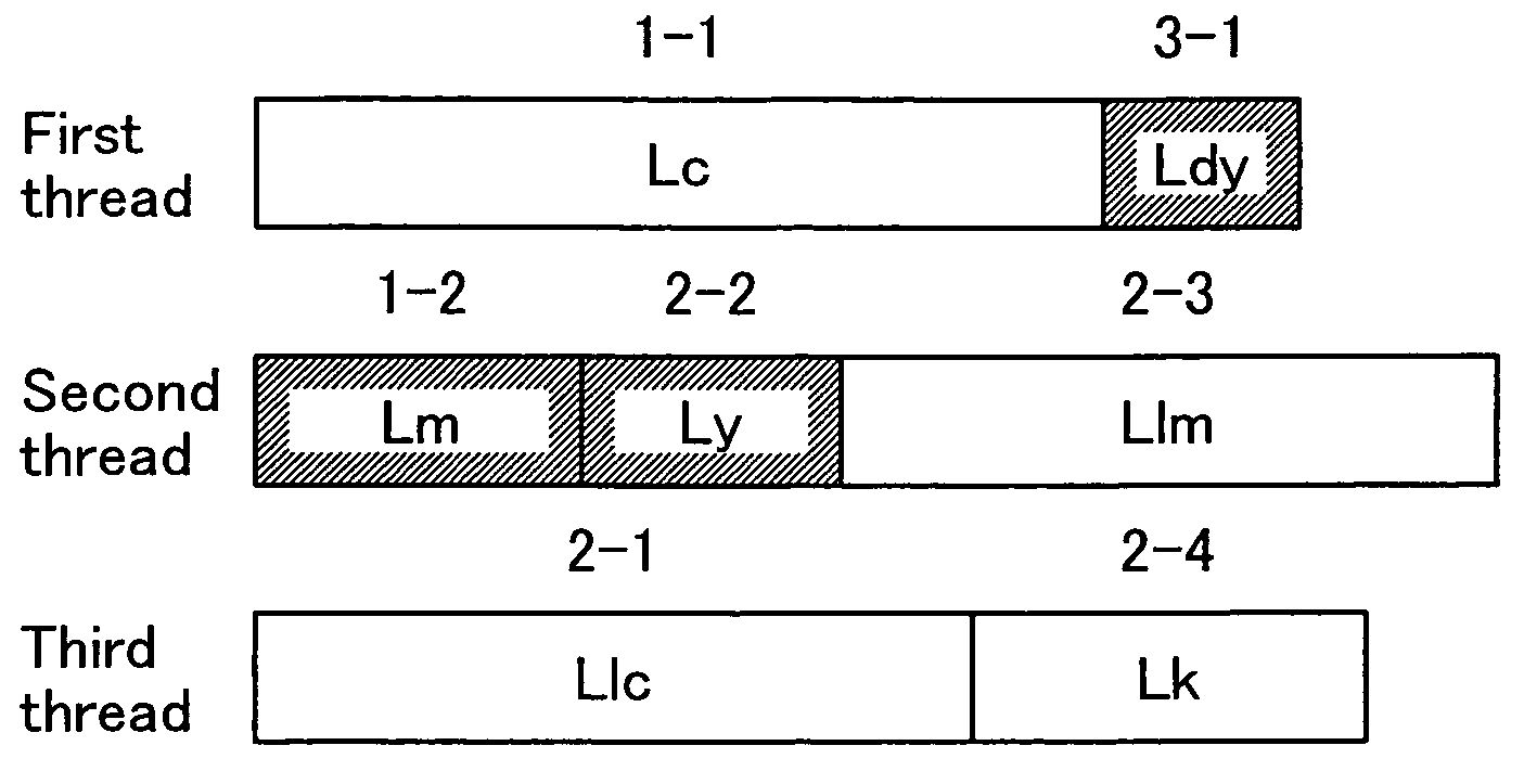
[0104]FIG. 9 shows the unit HT process segments allocated to the first through third threads for the third embodiment. With the third embodiment, there are three threads. The other points are the same as with the first embodiment.

[0105]At step S60 in FIG. 5, the allocation of sequence positions to the unit HT process segments is done as shown in FIG. 6B. Note that with the third embodiment, the number of the start group G1 unit HT process segments is lower than the number of threads. After that, at step S70 of FIG. 5, the unit HT process segments are allocated. The method of the allocation is the same as that of the first embodiment. Specifically, first, the start group G1 unit HT process segments are allocated to each thread, and after that, the middle group and the end group unit HT process segments are allocated to the thread with the lowest total load of allocated unit HT process segments according to the priority sequence.

[0106]With this kind of aspect as wel...


PUM


Abstract

For image processing for repeatedly executing process segment sets including N (N is an integer of 3 or greater) unit process segments Lc, Lm, Ly, Lk, Llc, Llm and Ldy, unit process segments are executed by M (M is an integer of 2 or greater but less than N) processing units. The unit process segments include a first-type unit process segments Lc, Llc, Llm, and Lk for performing processing using a first processing method and a second-type unit process segment Lm, Ly and Ldy for performing processing using a second processing method that is different from the first processing method. Then, when executing process segment sets, the M unit process segments including at least one each of the first-type and the second-type unit process segments Lc, Lm are first executed on the M processing units.

Description

BACKGROUND OF THE INVENTION[0001]1. Field of the Invention[0002]The present invention relates to technology for executing parallel image processing.[0003]2. Description of the Related Art[0004]There has been developed a parallel processing technology for use in converting image data expressing tone values of each color of ink of each pixel to image data expressing the absence or presence of ink color dots for each pixel. For example, in JP2000-293674A, disclosed is technology for executing rasterizing (data rearranging) processing and halftone processing according to the processing contents using separate threads.[0005]However, for the technology noted above, there was no consideration for efficient execution of each thread of the halftone processing of each color allocated to each processing unit.[0006]An object of the present invention is to provide a technology for efficiently executing parallel image processing.[0007]The present invention is related to Japanese patent applicatio...

Claims


Application Information

Patent Timeline
Patent Type & Authority Patents(United States)
IPC IPC(8): H04N1/52H04N1/405G06F9/46H04N1/46G06K15/00H04N1/40
CPCG06F9/3814G06F9/3851G06F9/5066G06F9/505G06F2209/5019
Inventor YAMAZAKI, SATOSHIKAKUTANI, TOSHIAKITAKATA, TERUYUKIUTSUNOMIYA, KOHEI
Owner SEIKO EPSON CORP
Why Eureka
Try Eureka