Electroacoustic devices with noise-reducing capability

a technology of electroacoustic devices and noise reduction, applied in the direction of active noise control, instruments, electrical transducers, etc., can solve the problems of phase shift between the original signal and the attenuated signal, the combination of active noise attenuation and passive noise attenuation, frequency response and phase response, etc., to minimize the adverse noise reduction effect and minimize direct sound reflection

Inactive Publication Date: 2008-12-16
MOSELEY WILLIAM T
View PDF9 Cites 114 Cited by
  • Summary
  • Abstract
  • Description
  • Claims
  • Application Information

AI Technical Summary

Benefits of technology

[0008]The present invention is generally directed to new and improved electroacoustic devices each including one or more microphones typically mounted on a baffle plate and disposed in substantially the same acoustic plane as a speaker or speakers. In the various embodiments, at least one microphone and at least one speaker face the same or opposite directions. In one embodiment, a microphone faces the same direction as the speaker or speakers and is oriented in the same plane as the baffle plate. In another embodiment, the microphone faces the same direction as the speaker or speakers and is oriented at an angle with respect to the plane of the baffle plate. In still another embodiment, the microphone and the speaker or speakers face opposite directions and the microphone is disposed in the same plane as the baffle plate. In yet another embodiment, the microphone and the speaker or speakers face opposite directions and the microphone is disposed at an angle with respect to the plane of the baffle plate. In other embodiments, one microphone faces the same or opposite direction as the speaker or speakers and is disposed in the same plane as the baffle plate or at an angle with respect to the plane of the baffle plate. Another microphone faces the same or different direction as the speaker or speakers and is disposed in the same plane as the baffle plate or at an angle with respect to the plane of the baffle plate. In other embodiments, the speaker includes a central opening or cavity in which a microphone having one of various orientations is provided. The orientations of the microphone or microphones with respect to the speaker or speakers minimize adverse noise reduction effects associated with the differences in sensitivities, frequency responses and phase responses and acoustic time delays between the microphones and the speaker or speakers, as well as minimize direct sound reflections that are picked up by the microphone or microphones.

Problems solved by technology

This type of noise-canceling capability results from a combination of active noise attenuation and passive noise attenuation.
One of the problems inherent in conventional active noise reduction designs for headphones is that the microphone or microphones and the speaker used in the headphone have sensitivities, frequency responses and phase responses which differ from each other.
Furthermore, the acoustic time delay between the microphone and the speaker causes a phase shift between the original signal and the attenuated signal.
Another problem that exists in active noise reduction designs is that the microphone or microphones tend to pick up direct reflections of certain frequencies of the original signal.

Method used


Image

  • Electroacoustic devices with noise-reducing capability
  • Electroacoustic devices with noise-reducing capability
  • Electroacoustic devices with noise-reducing capability

Examples


first embodiment

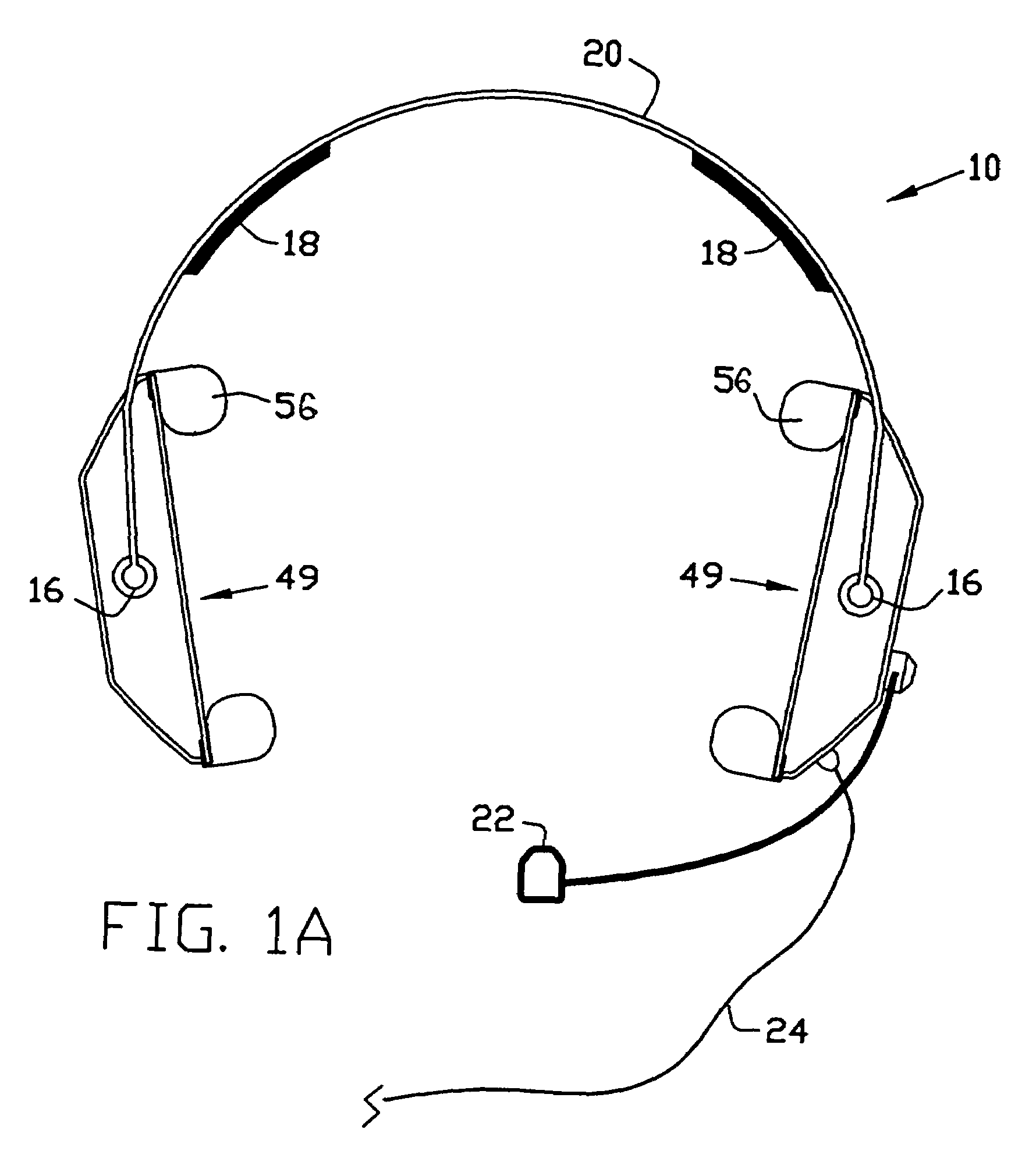
[0045]An illustrative embodiment of an electroacoustic device of the present invention is generally indicated by reference numeral 10 in FIG. 1A and includes a pair of transducer assemblies 49 connected to a pair of attachment points 16 of an adjustable headband 20, optionally including a pad 18. A boom microphone 22 may also be attached to a transducer assembly 49 or to the adjustable headband 20. One end of a cable 24 may be connected to the respective transducer assemblies 49, in which case the opposite end of the cable 24 is adapted for connection to an external device or devices (not shown). Alternatively, the transducer assemblies 49 may have internal electronic circuitry. While the electroacoustic device 10 in FIG. 1A and throughout the drawings is shown in the configuration of a headset, it will be understood that the present invention is equally adaptable to use as a telephone handset, a helmet or other electroacoustic device. Furthermore, the electroacoustic device 10 can ...

second embodiment

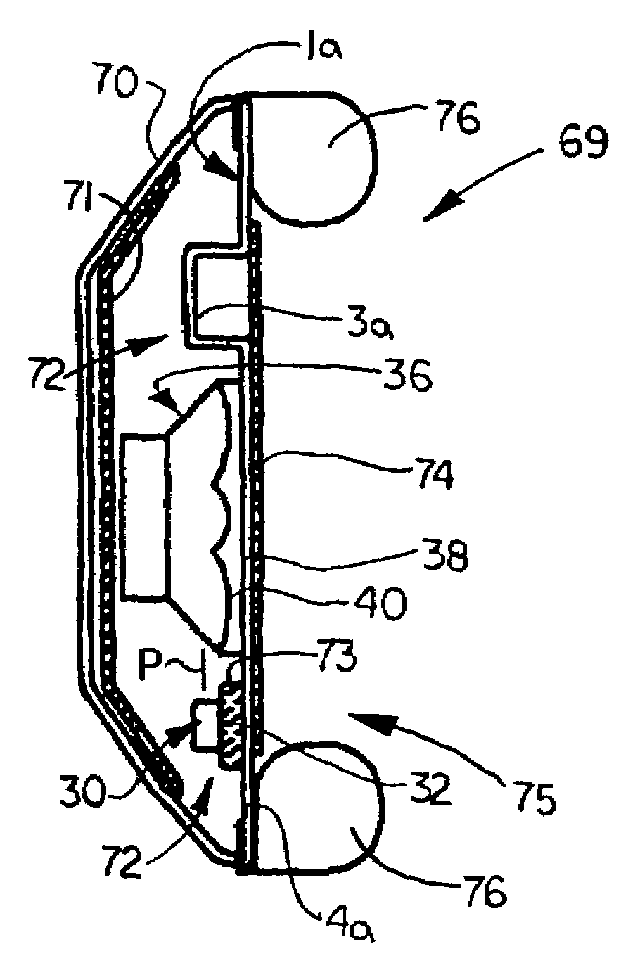
[0058]Referring next to FIG. 7A, in a second embodiment each transducer assembly 69 includes a generally concave housing 70 and a piece of outer acoustic foam 71 typically provided on the interior surface of the housing 70. A parallel cavity flat baffle plate 1a, heretofore described with respect to FIG. 5A, is mounted to the housing 70 to define an outer cavity 72 between the housing 70 and the rear surface of the parallel cavity flat baffle plate 1a, with the outer acoustic foam 71 provided in the outer cavity 72. A speaker 36 is typically mounted to the rear surface of the baffle plate 1a, with the front 38 of the speaker 36 disposed in communication with the speaker opening 2a (FIG. 5A) in the baffle plate 1a. A piece of microphone acoustic foam 73 is typically provided on the rear surface of the rim 4a of the baffle plate 1a, inside the outer cavity 72. The face 32 of a microphone 30 mounted to the baffle plate 1a faces the microphone acoustic foam 73. The diaphragm 34 (FIG. 2)...

third embodiment

[0060]Referring next to FIG. 8A, in a third embodiment each transducer assembly 119 includes a generally concave housing 120 which includes a housing extension 120a in the upper portion thereof to facilitate positioning of the interior transducer assembly components away from the ear 127a of a wearer. A piece of outer acoustic foam 121 is typically provided on the interior surface of the housing 120. A parallel cavity slant baffle plate 1c is mounted to the housing 120. An outer cavity 122 is defined between the housing 120 and the rear surface of the baffle plate 1c, with the outer acoustic foam 121 provided in the outer cavity 122. A speaker 36 is typically mounted to the rear surface of the baffle plate 1c, with the front 38 of the speaker 36 disposed in communication with the speaker opening 2c (FIG. 5C) in the baffle plate 1c. A generally flat piece of microphone acoustic foam 123a is provided in the microphone recess 3c of the baffle plate 1c. The face 32 of a first microphone...


PUM


Abstract

New and improved electroacoustic devices each including at least one transducer assembly having one or more microphones typically mounted on a baffle plate and disposed in substantially the same acoustic plane as a speaker or speakers. In the various embodiments, at least one microphone and at least one speaker face the same or opposite directions. Each microphone may be parallel to or oriented at an angle with respect to the speaker. In other embodiments, the speaker includes a central opening or cavity in which a microphone having one of various orientations is provided. The orientations of the microphone or microphones with respect to the speaker or speakers minimize adverse noise reduction effects associated with the differences in sensitivities, frequency responses and phase responses and acoustic time delays between the microphones and the speaker or speakers, as well as minimize sound reflections that are picked up by the microphone or microphones.

Description

CROSS-REFERENCE TO RELATED APPLICATIONS[0001]This application claims the benefit of U.S. Provisional application No. 60 / 528,528, filed Dec. 10, 2003.FIELD OF THE INVENTION[0002]The present invention relates to electroacoustic devices for translating electronic signals into acoustic signals perceived by the human ear. More particularly, the present invention relates to electroacoustic devices which include novel speaker and microphone configurations that are particularly effective in reducing noise perceived by a listener during use.BACKGROUND OF THE INVENTION[0003]Electroacoustic devices include headphones, headsets, helmets, speaker enclosures and other devices having electro-acoustic functions. Headphones typically include a pair of ear cups mounted on respective ends of an arcuate or C-shaped adjustable headband. Each of the ear cups contains a headphone speaker that converts electrical energy from a television, radio, compact disk (CD), cassette tape or the like into acoustic en...

Claims


Application Information

Patent Timeline
Patent Type & Authority Patents(United States)
IPC IPC(8): H04R25/00G10K11/16H04R1/10
CPCG10K11/1788H04R1/1008G10K2210/1081H04R1/1083G10K11/17857G10K11/17861G10K11/17875G10K11/17885
Inventor MOSELEY, WILLIAM T.
Owner MOSELEY WILLIAM T
Why Eureka
Try Eureka