Thermal energy recovery and management system

a technology of management system and thermal energy, applied in the direction of machines/engines, engine starters, transportation and packaging, etc., can solve the problems of significant additional vehicle cost and space requirements, and achieve the effects of minimizing engine wear, maximizing fuel efficiency, and minimizing emissions of exhaust gas

Active Publication Date: 2008-12-23
HANON SYST
View PDF28 Cites 26 Cited by
  • Summary
  • Abstract
  • Description
  • Claims
  • Application Information

AI Technical Summary

Benefits of technology

[0006]Harmonious with the present invention, a thermal energy recovery and management system for an internal combustion engine which stores a heated working medium in a insulated bottle which is released into the internal combustion engine operating system to minimize emissions in an exhaust gas from unburned hydrocarbons, maximize fuel efficiency, and minimize engine wear, especially during cold start conditions has surprisingly been discovered.

Problems solved by technology

The phase change materials currently used are typically corrosive and when used with working medium result in significant additional vehicle cost and space requirements.

Method used


Image

  • Thermal energy recovery and management system
  • Thermal energy recovery and management system
  • Thermal energy recovery and management system

Examples


Embodiment Construction

[0023]The following detailed description and appended drawings describe and illustrate various exemplary embodiments of the invention. The description and drawings serve to enable one skilled in the art to make and use the invention, and are not intended to limit the scope of the invention in any manner.

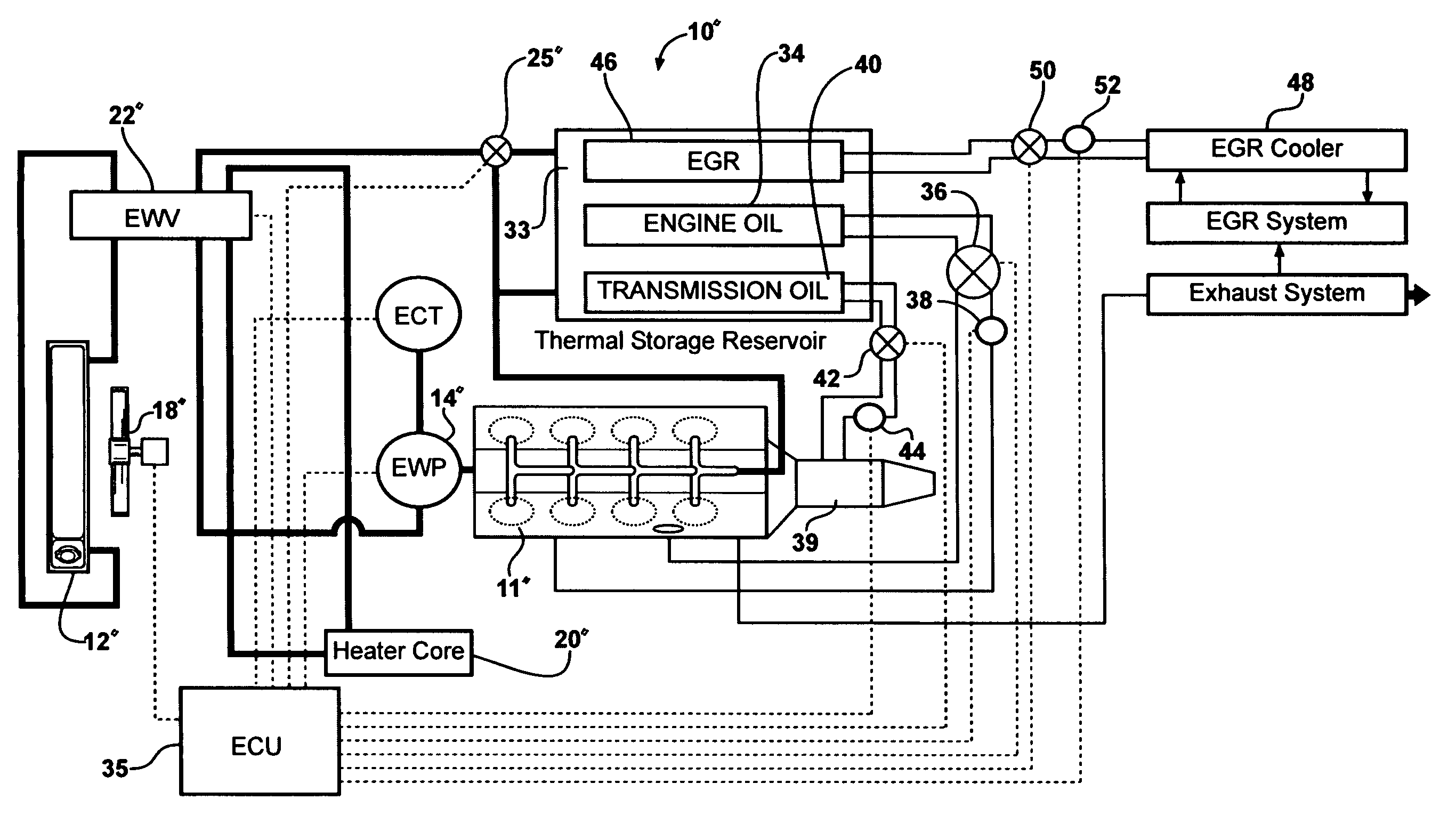
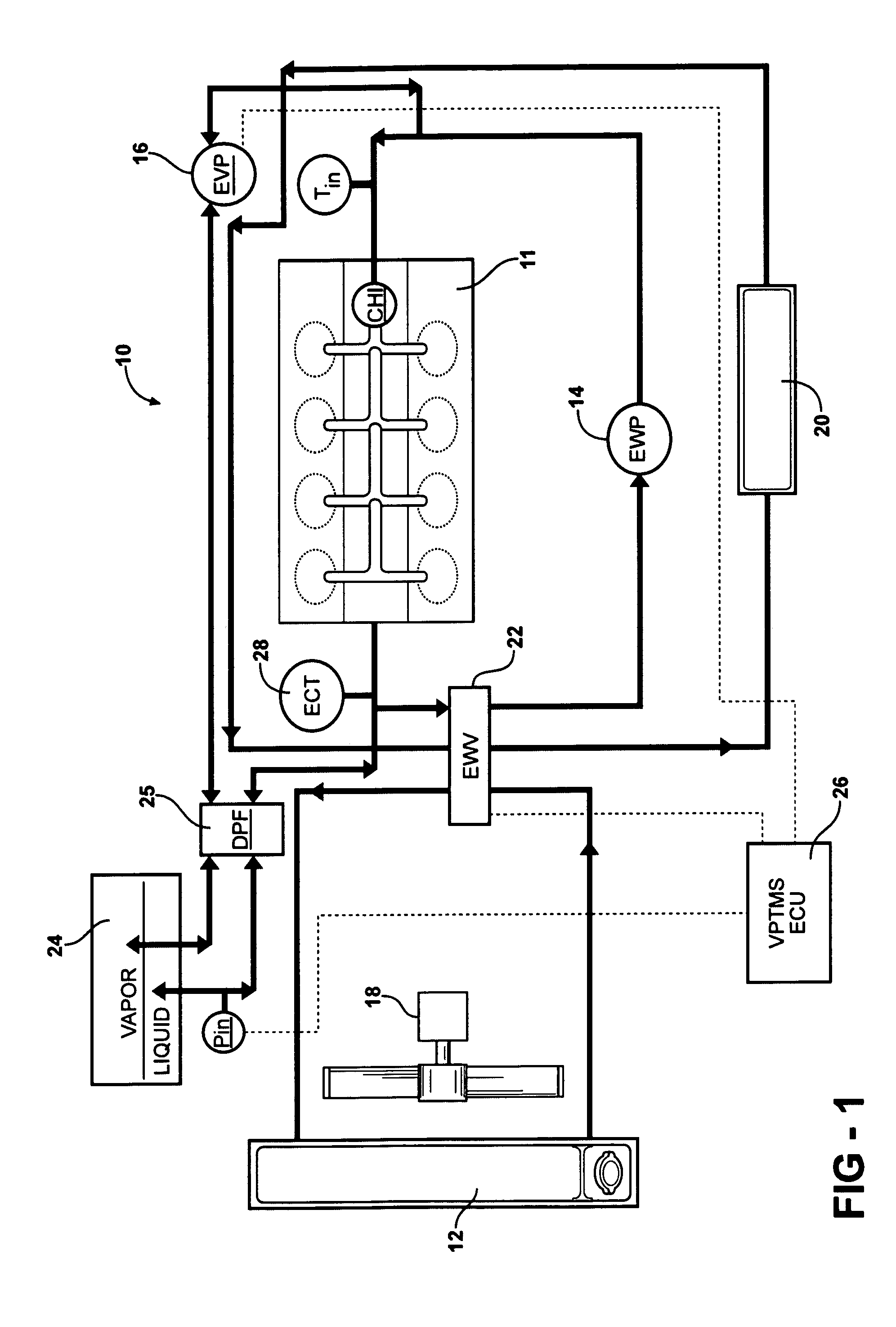
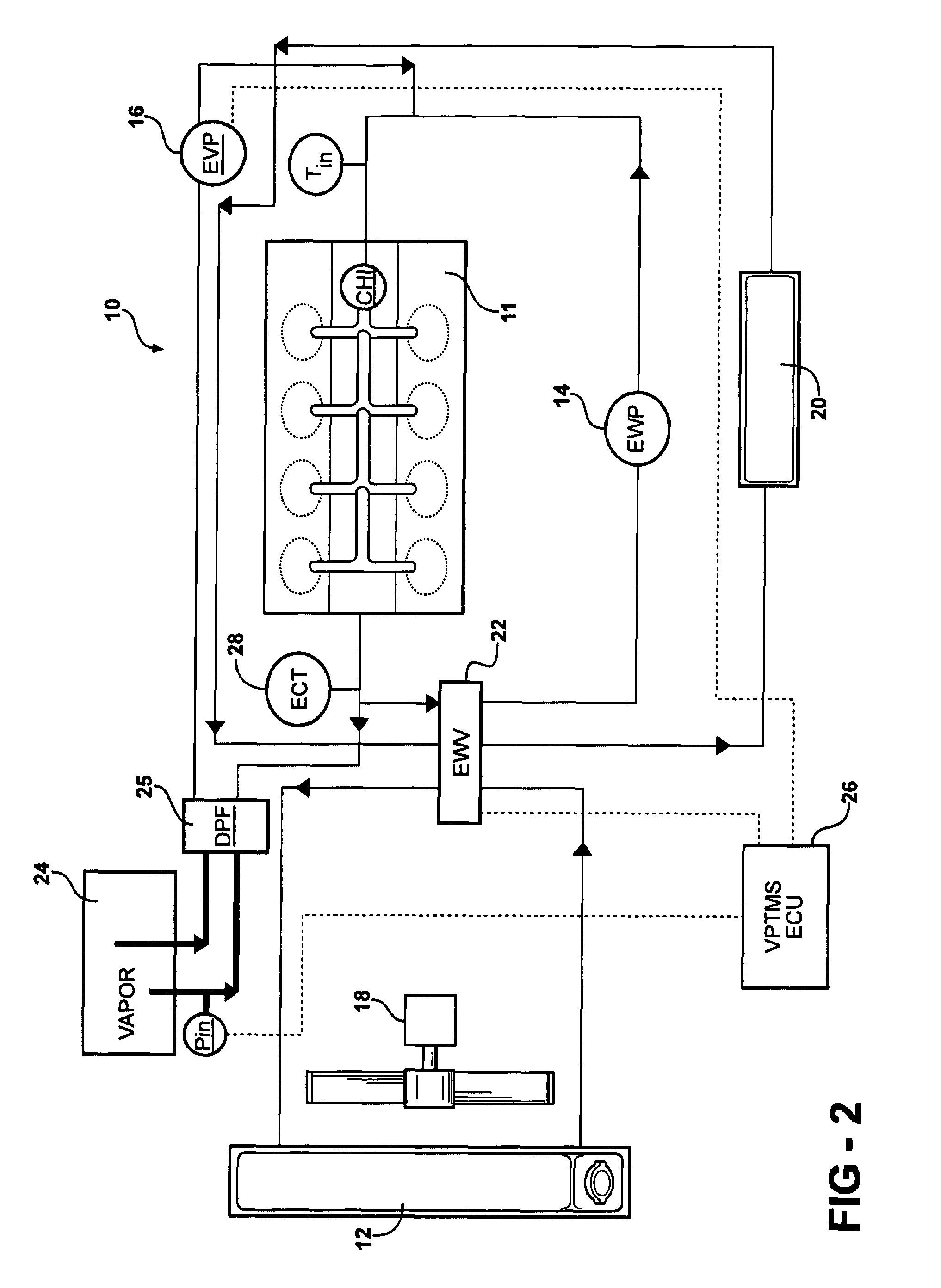
[0024]FIG. 1 shows a thermal energy recovery and management system 10 according to an embodiment of the invention. The system 10 includes an internal combustion engine 11, which is provided with a heating and cooling system. The heating and cooling system includes a cooling radiator 12, an electric water pump 14, an electric vapor pump 16, an electric fan 18, a heater core 20, a three position electric solenoid actuated valve 22, a thermal energy storage reservoir 24, a differential pressure valve 25 and an electric control unit 26. Although specific elements such as electric water pump, electric vapor pump, electric fan, and electric solenoid actuated valve are described herein, for...


PUM


Abstract

A thermal energy recovery and management system for an internal combustion engine for balancing the heat energy between a primary reservoir and the engine to maximize an operating efficiency of the engine and associated engine components. The primary reservoir storing or releasing heat energy produced by the engine to achieve a balance of energy between the engine and associated components.

Description

FIELD OF THE INVENTION[0001]The present invention relates to a thermal energy recovery and management system and more particularly to an energy recovery system capable of transferring heat energy to and from various components of an internal combustion engine for powering a vehicle to effect improved emission control, fuel efficiency, and engine durability.BACKGROUND OF THE INVENTION[0002]It is known that stored thermal energy may be employed to reduce exhaust emission pollutants from an internal combustion engine by facilitating engine warm-up. Stored thermal energy may also be provided to the engine to minimize engine warm-up time and reduce cold start engine-wear, thereby increasing engine durability. Further, the more rapidly the engine is heated, the quicker the engine will operate at increased efficiencies to improve fuel consumption characteristics.[0003]The broad concept of the utilization of thermal energy storage systems for internal combustion engines employing a thermal ...

Claims


Application Information

Patent Timeline
Patent Type & Authority Patents(United States)
IPC IPC(8): F01P7/02B60H1/03F02N17/02F02N17/06F02N19/02F02N19/10
CPCF01P11/20F01P2011/205F01P2060/08
Inventor SZALONY, NORMANHUNG, STEPHEN THINK
Owner HANON SYST
Why Eureka
Try Eureka