
Automatic transfer switch apparatus

a transfer switch and automatic technology, applied in the direction of motor/generator/converter stopper, magnetic body, emergency power supply arrangement, etc., can solve the problems of increasing the size and cost of the ats, increasing the real estate and wiring, and periodic maintenance of the ats system

Inactive Publication Date: 2008-12-23
ABB (SCHWEIZ) AG
View PDF3 Cites 24 Cited by
  • Summary
  • Abstract
  • Description
  • Claims
  • Application Information

AI Technical Summary

Benefits of technology

This solution results in a more compact, cost-effective ATS with reduced maintenance requirements, fewer components, and improved reliability by eliminating electromagnetic relay-related issues, such as mechanical wear and electrical arcing.

Problems solved by technology

However, in more complex systems, such as open transition ATSs where the switch of the ATS may be placed in an isolation position, a greater number of control components are required, which results in an ATS that requires additional real estate and wiring, thereby increasing the size and cost of the ATS.
Also, due to the switching characteristics of electromagnetic relays, preventative maintenance of the ATS system is periodically required.

Method used


Image

  • Automatic transfer switch apparatus
  • Automatic transfer switch apparatus
  • Automatic transfer switch apparatus

Examples


Embodiment Construction

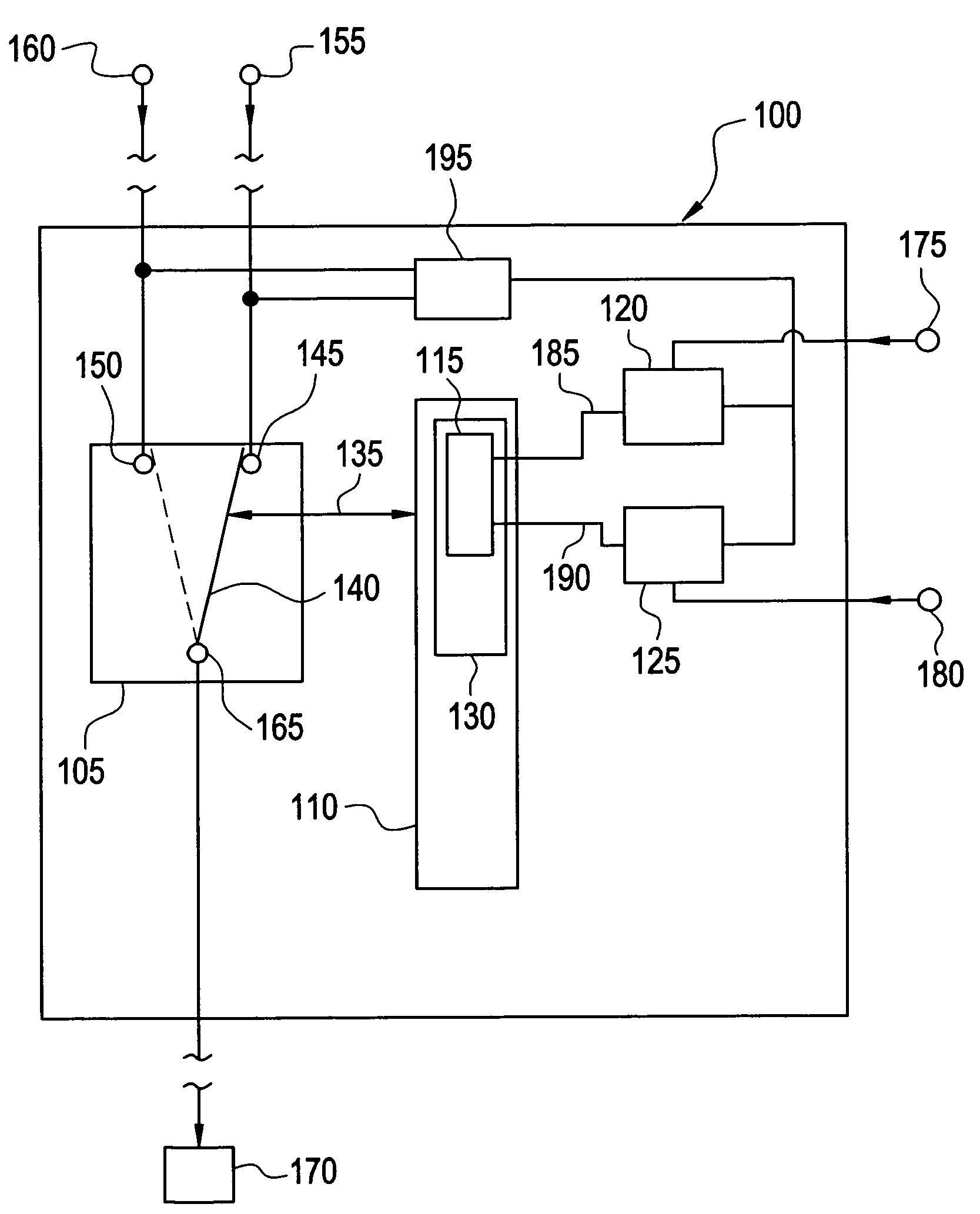
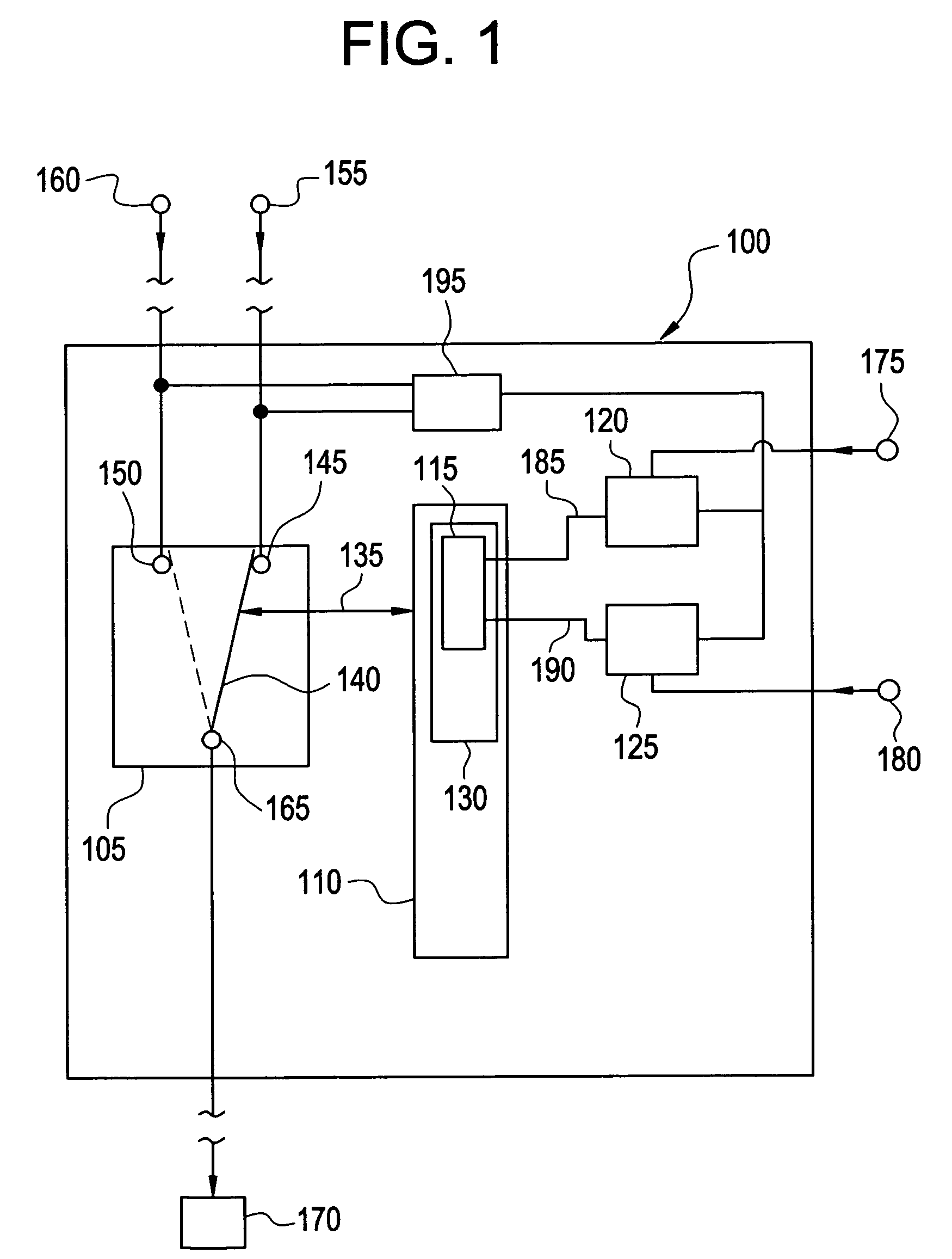
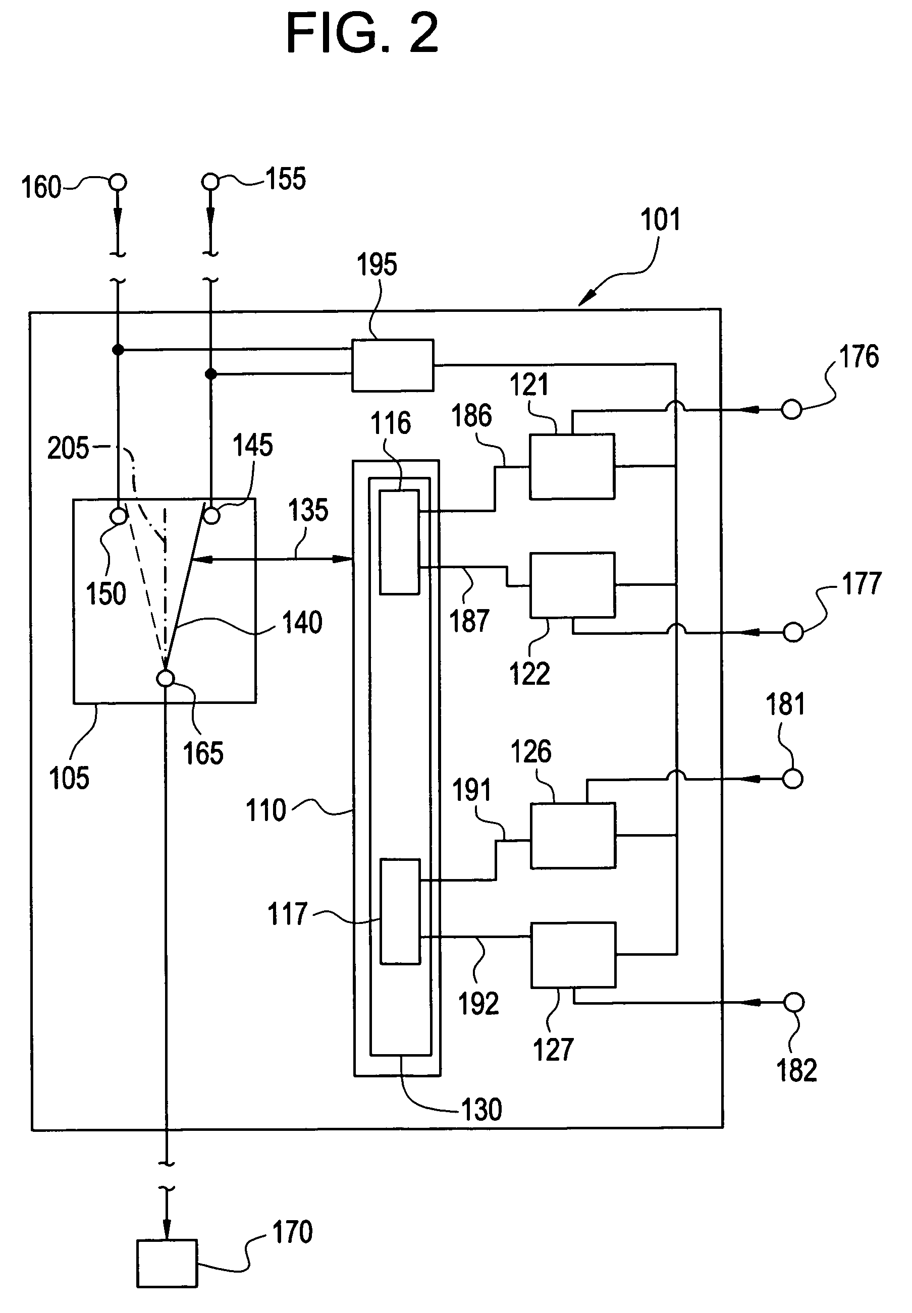
[0011]An embodiment of the invention provides an Automatic Transfer Switch (ATS) with a solid state control relay for energizing and driving a mechanical drive system that actuates the switch for switching between power sources. The solid state control relay is capable of converting AC power to DC power while simultaneously switching ON and OFF high voltage (120 VAC to 600 VAC for example) and high current signals to a main drive solenoid on contactor style ATSs. While an embodiment of the invention described herein depicts as an example a mechanical drive system having a solenoid driving a power contactor, which in turn powers a motor operated mechanism for switching between power sources, it will be appreciated that the disclosed invention is also applicable to other drive systems, such as one actuated by a linear motor for example. Embodiments of the invention may be used in, but are not limited to, the industrial and commercial markets throughout the U.S. and the World where ATS...


PUM

PropertyMeasurementUnit
DC voltageaaaaaaaaaa
time delayaaaaaaaaaa
AC voltageaaaaaaaaaa

Abstract

An Automatic Transfer Switch (ATS) having a switch configured to connect one of two sources to a load, a mechanical drive, an actuator, and a solid state control relay is disclosed. The mechanical drive is configured to drive the switch between a first position and a second position, the first position connecting the switch to the first source, and the second position connecting the switch to the second source. The actuator is in mechanical communication with the mechanical drive to cause the mechanical drive to move on command. The solid state control relay is responsive to an external signal and productive of a control signal, wherein the actuator is responsive to the control signal to cause the mechanical drive to move.

Description

BACKGROUND OF THE INVENTION[0001]The present disclosure relates generally to electrical distribution systems, and particularly to Automatic Transfer Switches.[0002]Electrical distribution systems employ a variety of devices for controlling and managing the distribution of electrical power, including Automatic Transfer Switches. In general, an Automatic Transfer Switch (ATS) is a device that connects one of two power sources to a load, so that the load may receive electrical power in the event that one of the power sources becomes non-operational. Such devices are often employed in applications requiring emergency backup power generation, such as hospitals for example, where the primary source of power comes from a utility grid, and the alternate source of power comes from a backup generator. Many of the known ATSs employ electromagnetic switching relays coupled with rectifiers to provide control power and signaling to operate the switch of the ATS system. In these types of systems, ...

Claims


Application Information

Patent Timeline
Patent Type & Authority Patents(United States)
IPC IPC(8): H02J9/06
CPCH02J3/005H02J9/06H02J3/007
Inventor SERRANO, MARK ANTHONYSHAMIEH, FAROOGKRCHAK, KENNETH C.
Owner ABB (SCHWEIZ) AG
Learn More