Compliant coupling force control system

a coupling force and control system technology, applied in the direction of electric programme control, force/torque/work measurement apparatus, instruments, etc., can solve the problems of high cycle rate, difficult to follow, accelerated fatigue, etc., to reduce control errors, accelerate fatigue, and accelerate the cycle rate

Active Publication Date: 2008-12-30
THE BOEING CO
View PDF17 Cites 9 Cited by
  • Summary
  • Abstract
  • Description
  • Claims
  • Application Information

AI Technical Summary

Benefits of technology

[0017]Another advantage of the present invention is the provision of a volute spring force compliant member within a force control system. The volute spring member restrains the received output from a force compliant mechanism to a single degree-of-freedom motion.
[0018]Yet another advantage of the present invention is the provision of a force control system for actuation and testing of a test object that introduces velocity compensation into the generation of a force that is applied on the test object. The velocity compensation may be introduced in a feedforward or a feedback configuration. The velocity compensation increases and provides accurate control of the test object without the need for integral compensation and provides increased stability in the control system. This compensation also allows for quicker cycling of the test object since the load feedback better follows the force command.
[0019]Furthermore, another advantage provided by an embodiment of the present invention is the provision of a force control system that incorporates pressure corrected velocity compensation, which reduces control error. The pressure compensation compensates for the change in available pressure drop across a servo valve.
[0020]Still another advantage provided by an embodiment of the present invention is the provision of a force control system with acceleration compensation. This reduces effects of inertia by compensating for the mass of the actuator linkage components.
[0021]Moreover, the present invention provides compensation in real time rather than using simply historical information, which is inadequate in a dynamic application. This real time compensation provides mathematically correct compensation magnitudes.
[0022]A similar improved quality of force control can be achieved by implementing an algorithm in a force control system that generates both a force command signal and a stroke command signal in a feedforward configuration. This too provides velocity compensation and minimizes control errors and improves performance accuracy.

Problems solved by technology

The actuators must work in unison to flex the structure and cause accelerated fatigue.
Some tests require high cycle rates, which can be difficult to follow due to changing dynamics experienced by the actuators.
When this load is applied using hydraulic actuators and servo valves with classical control methods, the resulting accuracy may be unacceptable at maximum rated pressures and flows.
There may be inaccuracy in the applied force relative to the commanded force signals due to motion of the object.
Force control systems can also experience lack of symmetry in system polarity.
This is especially true when utilizing single ended actuators, in which the amount of lack of symmetry is significant.
The lack of symmetry can be due to differences in tubing connections, servo valves, and other components and devices.
However, the increased gain may only marginally reduce the error and leads to limit cycling or oscillation and instability in the force control loop.
Even with the increased gain, these types of force control systems may not be robust when null shifts occur in the equipment.
Null shifts may cause a proportionate amount of force errors to accumulate.
Thus, these systems are partially uncontrolled systems and may only be marginally stable and as error increases the systems may become unstable and may be sensitive to null shifts in the hardware.
Although useful for static conditions, error integration can cause instability during transitions in force polarity.
This added time constraint reduces the benefit of using integral compensation on durability tests that have fast changing set point commands.
This method tends to be slow, which results in larger errors for longer time intervals.
The errors are larger due to the increased time for the damping algorithm to correct for the velocity.
These systems overcome steady state errors, increased settling time, and other associated disadvantages commonly associated with force control systems.
However, another common associated disadvantage of force control systems may be an inability to account for force transients.
Force transients can also occur due to vibrations, shocks, or large abrupt random forces exerted on the system.
This unfortunately may tend to reduce the accuracy, increase errors, and reduce bandwidth or system response.
The stated methods have resulted in marginal stability, reduced stability, stability over limited frequency bandwidth, limits in force output, large, heavy, and expensive actuators, and / or an increase in phase lag at certain frequencies.
Increasing the response of a servo control system may be ineffective because the transient disturbance rate is high.
Some force control systems as designed are incapable of being easily altered to provide improved stability.
In addition, the motion that causes the force transients may be activated by a mechanism that is quicker than the associated force control system, thus preventing the system from being able to account for such transients.

Method used


Image

  • Compliant coupling force control system
  • Compliant coupling force control system
  • Compliant coupling force control system

Examples


Embodiment Construction

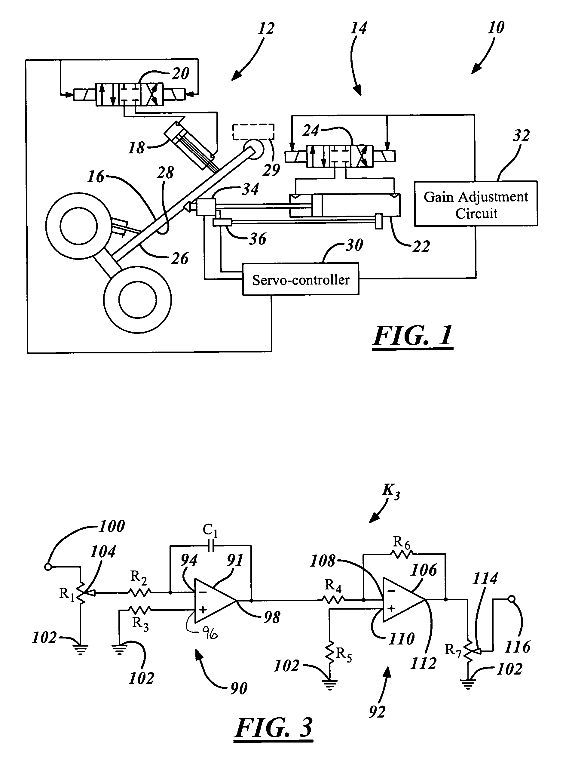
[0061]One technique of reducing force transients in a hydraulic powered system is to add a passive compliant mechanism between a servovalve and an actuator of a force control system. This technique uses accumulators on force actuator ports of the system. The compliance, however, lowers the phase margin of the hydraulic system. As a result, the instability reached using the stated technique while meeting increased gain requirements, limited the effectiveness.

[0062]Another technique used to reduce force transients in a hydraulic powered system is to increase the gain of a force control system. In order to increase the gain, and avoid instability, compensation is added to the control loop using numerous methods. These methods do not provide a substantive reduction in the amplitude of force transient phenomena.

[0063]Yet another technique used to reduce force transients in a hydraulic powered system is to add damping to a force control actuator by connecting the ports thereof through a c...


PUM


Abstract

A force compliant mechanism (750) for a force control system (600) includes a housing (752). A force compliant volute spring member (754) that has an input end (790) and an output end (792) is disposed within the housing (752). A force actuator input shaft (798) operates in response to a force induced thereon. An output shaft (800) is coupled to the output end (792) and to a test object (802). A force transducer (780) is in operative coupling with the force actuator input shaft (798) and generates a force signal in response to the induced force. A method of reducing force transients and increasing stability within a force control system (660) includes applying a force on a test object (666). A force actuator (669) is decoupled from the test object (666). The overall stiffness of the force control system is reduced and dynamic energy is absorbed via a force compliant member (662) coupled to the test object (666) and the force actuator (669).

Description

RELATED APPLICATION[0001]The present invention is related to U.S. patent application Ser. No. 11 / 221,006, filed Sep. 7, 2005, entitled “VELOCITY FEEDBACK COMPENSATION FOR FORCE CONTROL SYSTEMS”, and issued as U.S. Pat. No. 7,281,431 on Oct. 16, 2007, which is incorporated by reference herein.TECHNICAL FIELD[0002]The present invention relates generally to force control systems and to vehicle and component testing systems. The present invention is related to the accurate controlling of applied force and the direction of that force on a component or system under test. More particularly, the present invention is related to a technique for providing tensile, compressive, and torsional compliance with minimal degrees of freedom for motion in a force control system.BACKGROUND OF THE INVENTION[0003]Vehicle systems and components are tested during the development and manufacturing thereof using various techniques. The systems and components undergo static, quasi-static, and dynamic testing t...

Claims


Application Information

Patent Timeline
Patent Type & Authority Patents(United States)
IPC IPC(8): F16F1/10
CPCB64C25/22G05B19/19F15B2211/6656F15B2211/6336
Inventor ENGLUND, NORMAN J.FINIGAN, JOHN S.
Owner THE BOEING CO
Why Eureka
Try Eureka