Spring carrier with adustable spring collar

a spring collar and spring technology, applied in the field of spring collars, can solve the problems of increased friction between the piston rod and the piston rod guide, loss of driving comfort, and difficulty in removing the vibration damper when it needs to be repaired, and achieve the effect of greatest possible elasticity and easy assembly

Inactive Publication Date: 2008-12-30
ZF FRIEDRICHSHAFEN AG
View PDF9 Cites 93 Cited by
  • Summary
  • Abstract
  • Description
  • Claims
  • Application Information

AI Technical Summary

Benefits of technology

[0009]The task of the present invention is to realize a spring carrier which can be assembled easily with a vibration damper and to ensure that the vibration damper is supported with the greatest possible elasticity.
[0011]The second resilient mount can absorb the high-frequency excitations of the piston rod caused by the damping forces, so that no bothersome noises are transmitted to the body of the vehicle.
[0017]The guide tube can be divided at a certain point along its length. By means of this measure, it is easier to gain access to the bearings located between the threaded spindle and the guide tube.
[0018]It is also possible to connect the guide tube to the housing of the actuator. This provides the guide tube with a very strong mounting.

Problems solved by technology

As a result, however, a transverse force is generated inside the vibration damper, which leads to an increase in the friction between the piston rod and the piston rod guide (not shown).
As a result, the increase in static friction in the vibration damper leads to a loss of driving comfort.
Another disadvantage of this spring carrier is that it is very difficult to remove the vibration damper when it needs to be repaired.
On closer consideration, it is obvious that the installation of the vibration damper must also be rather complicated, because the thrust stop is peened onto the piston rod, and the threaded spindle has a much smaller inside diameter than the outside diameter of the thrust stop.

Method used


Image

  • Spring carrier with adustable spring collar
  • Spring carrier with adustable spring collar
  • Spring carrier with adustable spring collar

Examples


Embodiment Construction

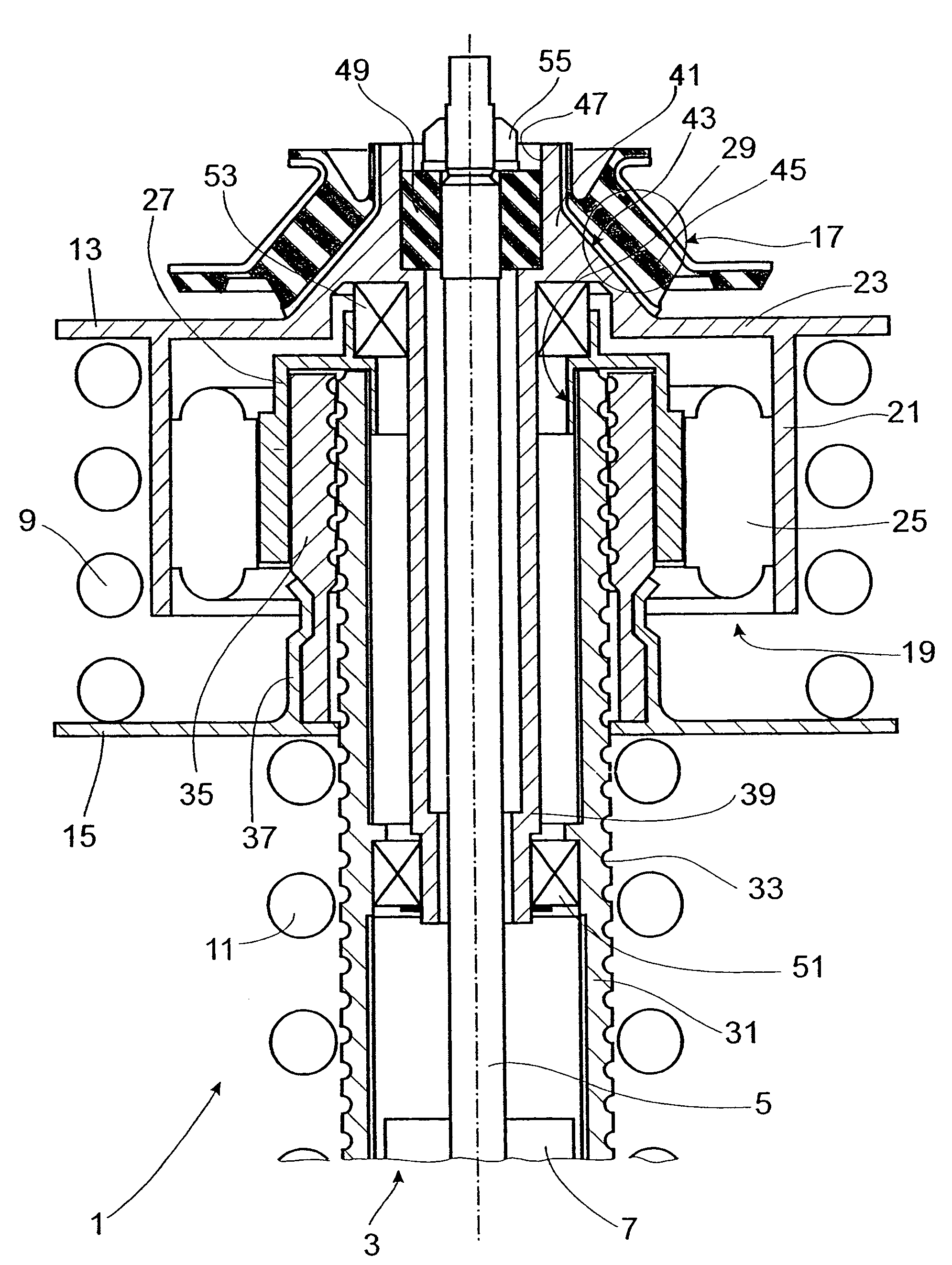
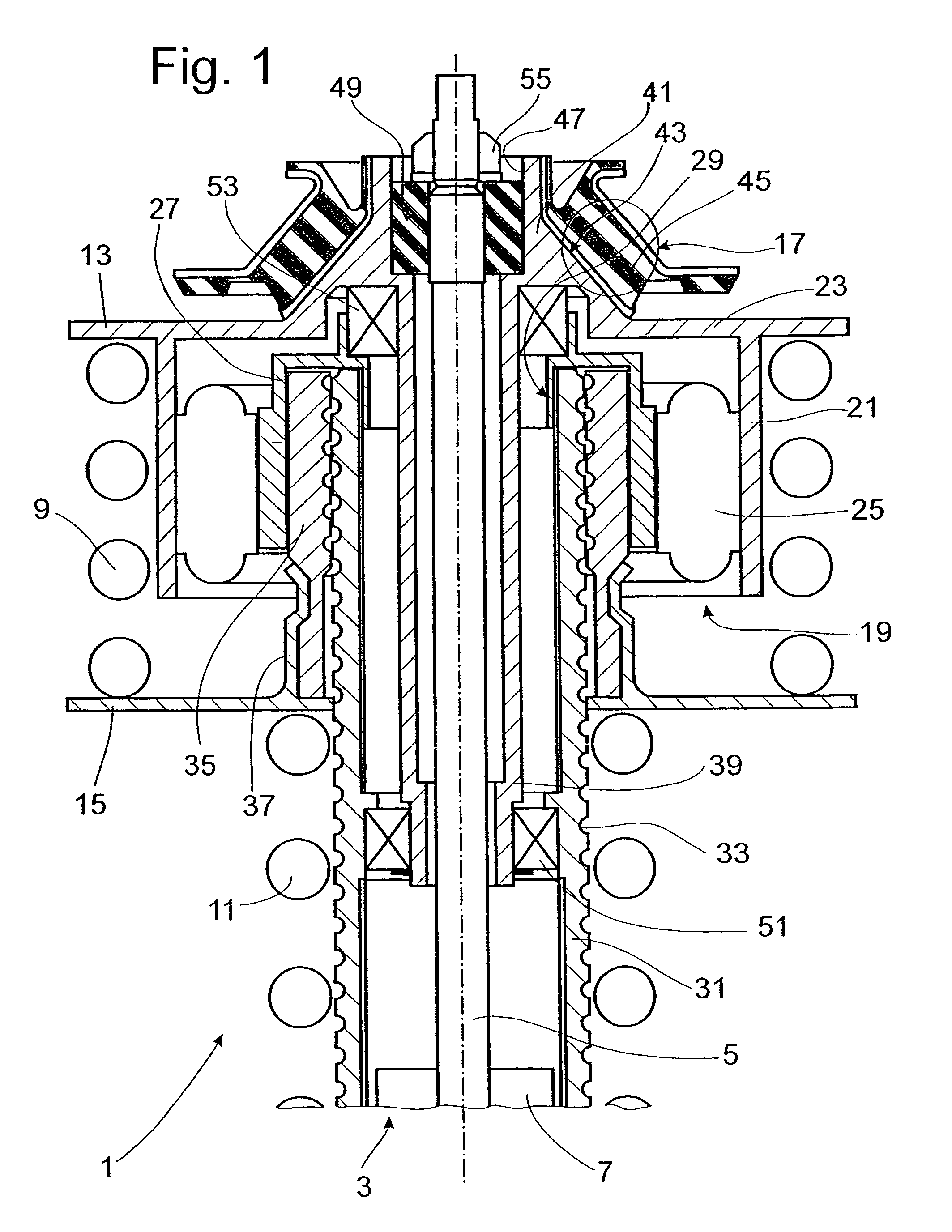
[0024]FIG. 1 shows the upper part of a spring strut 1, which is installed, for example, between a vehicle axle (not shown) and a vehicle body. A vibration damper 3, known in and of itself, includes an axially movable piston rod 5 in a cylinder 7, and is surrounded by a first spring 9 and a second spring 11. The first spring 9 is clamped between a first spring collar 13 and a second spring collar 15. The second spring 11 is located between the bottom side of the second spring collar 15 and a third spring collar (not shown), which is attached optionally either to the cylinder 7 or to a part of the vehicle axle. The upper spring collar 13 is connected by a universally resilient mount 17 to the vehicle body. A rotary drive 19 in the form of an electric motor is also attached to this head bearing. The rotary drive comprises a housing 21 with an end part 23, which forms a one-piece unit with the upper spring collar 13.

[0025]In the housing 21, a ring-shaped stator 25 is installed, which dr...


PUM


Abstract

A spring carrier for mounting a spring strut to a vehicle body includes a vibration damper having a cylinder and a piston rod which is axially guided in the cylinder, first and second spring collars, and a spring located between the spring collars. An actuator includes a nut and a threaded spindle surrounding the piston rod, the actuator being driven to change the relative axial position of the spring collars. A guide tube extends coaxially between the piston rod and the threaded spindle, the guide tube being fixed to the vehicle body by a first resilient mount, the piston rod being fixed to the guide tube by a second resilient mount, whereby the piston rod can move relative to the first resilient mount.

Description

BACKGROUND OF THE INVENTION[0001]1. Field of the Invention[0002]The invention relates to spring carrier for mounting a spring strut to a vehicle, including a vibration damper including a cylinder and a piston rod which is axially guided in the cylinder, first and second spring collars with a spring therebetween, and an actuator which is driven to change the relative axial position of the spring collars.[0003]2. Description of the Related Art[0004]A vehicle chassis which comprises a spring carrier with an adjustable spring collar for a suspension spring is known from DE 102 55 764 B3, which represents the underlying state of the art. To actuate the spring collar, an actuator designed as an electric motor is used, which drives a hollow threaded spindle. A threaded nut is mounted on the actuating thread of the threaded spindle, and this nut is connected in turn to an adjustable spring collar. The rotary motion of the rotor is converted by the combination of the spindle and the threaded...

Claims


Application Information

Patent Timeline
Patent Type & Authority Patents(United States)
IPC IPC(8): B60G17/00B60G15/00
CPCB60G15/065B60G17/021F16F15/02B60G2202/12B60G2202/312B60G2202/42B60G2204/124B60G2204/1242B60G2204/128B60G2500/20B60G2500/30B60G2800/914
Inventor MUNSTER, MARTINMAIR, ULRICHBAASCH, DETLEF
Owner ZF FRIEDRICHSHAFEN AG
Why Eureka
Try Eureka