Shift system for outboard motors

a technology of shifting system and outboard motor, which is applied in the direction of propulsive elements, marine propulsion, vessel construction, etc., can solve the problems of increasing the size of the whole shift system, increasing the size of the motor-driven shift actuator, and unable to meet the requirements of a conventional outboard motor. , to achieve the effect of reducing the siz

Active Publication Date: 2008-12-30
SUZUKI MOTOR CORP
View PDF4 Cites 3 Cited by
  • Summary
  • Abstract
  • Description
  • Claims
  • Application Information

AI Technical Summary

Benefits of technology

[0007]The present invention provides a shift system for outboard motors, which is reduced in size, and is capable of securing compatibility with an outboard motor of a type for which the shift operation is manually performed using a shift cable.
[0009]With this arrangement, it is possible to reduce the size of the system and secure compatibility with an outboard motor of a type for which the shift operation is manually performed using a shift cable.
[0011]With this arrangement, it is possible to maintain the shift system compact in size in spite of the presence of the neural switch.
[0013]With this arrangement, it is possible to maintain the shift system compact in size in spite of the presence of the position sensor.
[0015]With this arrangement, it is possible to provide a high damping effect with the compact arrangement.
[0017]With this arrangement, it is possible to ensure excellent operability in switching to the shift operation using a shift cable.

Problems solved by technology

However, in the shift system disclosed in Japanese Laid-Open Patent Publication (Kokai) No. 2004-245350, the motor-driven actuator is connected to a shift rod via a plurality of reduction gears and shift rod-side gears and the like, and hence it is difficult for the shift system be compatible with a conventional outboard motor of a type for which the shift operation is manually performed using a shift cable.
On the other hand, the shift system disclosed in Japanese Laid-Open Patent Publication (Kokai) No. 2004-244003 is designed without giving sufficient consideration to the orientation of a motor output shaft or the disposition of a motor-driven shift actuator, for compactness thereof, which results in an increase in the size of the whole shift system.
Furthermore, a neutral switch is incorporated in the motor-driven shift actuator, which increases the size of the motor-driven shift actuator.

Method used


Image

  • Shift system for outboard motors
  • Shift system for outboard motors
  • Shift system for outboard motors

Examples


first embodiment

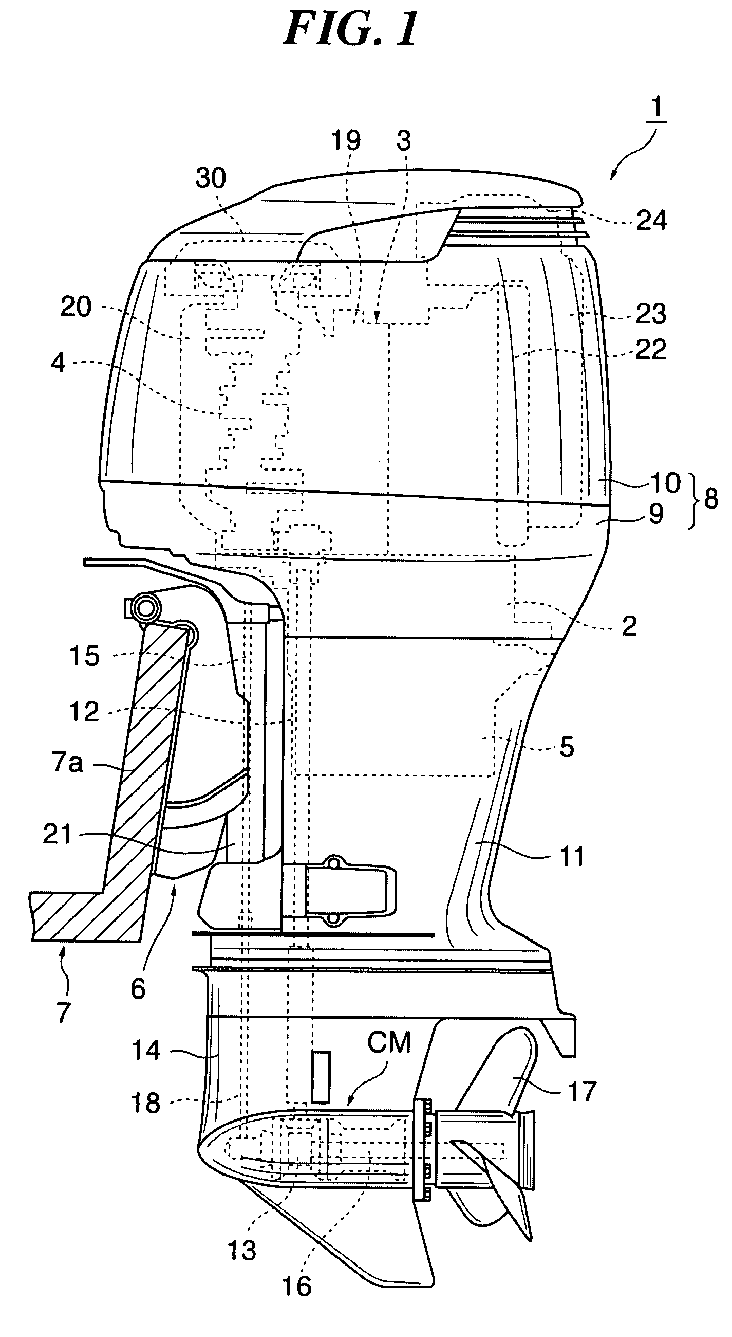
[0039]FIG. 1 is a left side view of an outboard motor to which is applied a shift system according to the present invention.

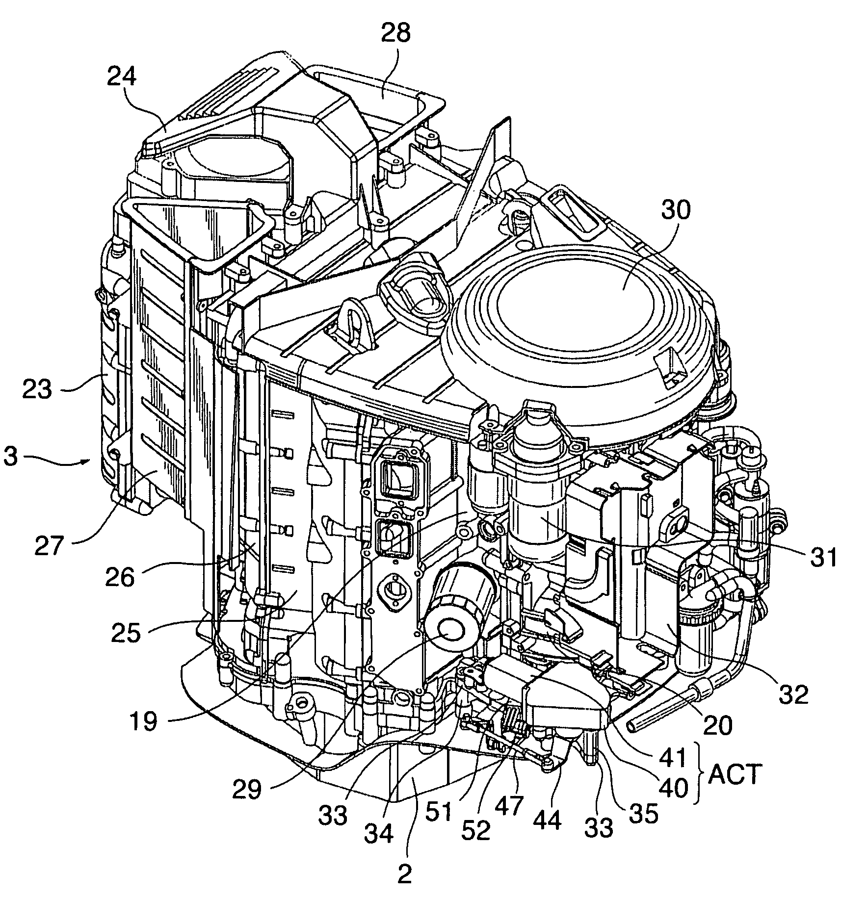
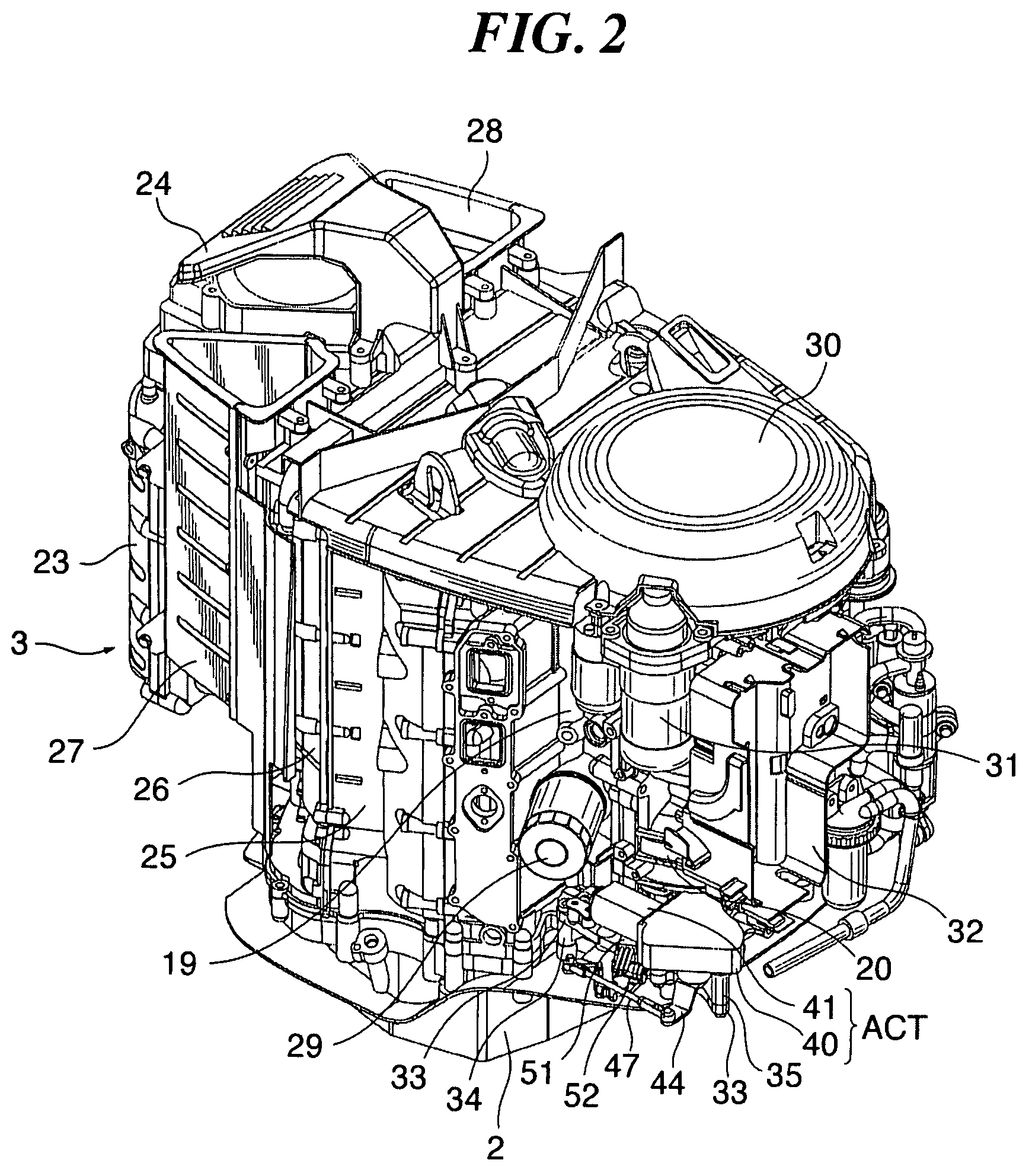
[0040]The outboard motor 1 includes an engine holder 2, and an engine 3 installed on the engine holder 2. The engine 3 is a vertical-type water-cooled four-cycle six-cylinder engine having a crankshaft 4 substantially perpendicularly installed therein.

[0041]Under the engine holder 2, there is disposed an oil pan 5 for storing lubricating oil. The outboard motor 1 has a bracket device 6 attached thereto, and is mounted to a transom 7a of a vessel 7 via the bracket device 6. Hereafter, the ship side of the outboard motor 1 will be referred to as “the front”, and a side toward the viewer, as viewed in FIG. 1, as “the left”. Further, the sides in the vertical direction will be referred to with reference to a tilt-down state (state shown in FIG. 1) of the outboard motor 1.

[0042]An engine cover 8 covers around the engine 3, the engine holder 2, and the oil pan 5. The...

second embodiment

[0079]FIG. 10 is a right side view corresponding to FIG. 5 but showing a first example of application of a damper to the shift system according to the In this example, each of the bolts 36 is screwed into an associated one of the supports 35 from below the clutch base 33 via a spacer 67 and a damper 66.

[0080]This variation makes it possible to provide a damping or cushioning function between the clutch base 33 and the actuator body 40, thereby suppressing repulsion and the like adverse effect caused by the operation of the actuator ACT.

[0081]FIG. 11 is a bottom view of a right front part of an engine holder 2, which corresponds to FIG. 4 but shows a second example of application of a damper to the shift system according to the second embodiment. FIG. 12 is a cross-sectional view taken on line A-A of FIG. 11. In this example, a damper 70 is provided between the left end of the second link member 63 and the clutch rod 15.

[0082]One end of an arm 68 corresponding to the arm 65 (see FIG...

third embodiment

[0095]FIG. 16A is a bottom view of a right front part of an engine holder in the shift system which corresponds to FIG. 4, and FIG. 16B is a cross-sectional view of the upper front part of the engine holder.

[0096]In this example, as shown in FIGS. 16A and 16B, the position sensor 51 is disposed on the upper end of the clutch rod 15 and fixed to the engine holder 2. The position sensor 51 is disposed coaxially with the clutch rod 15, and is configured to detect the rotational angle of the clutch rod 15 in place of the rotational angle of the clutch shaft 60. It should be noted that the position sensor 51 may not be disposed coaxially with the clutch rod 15, but it may be configured and disposed such that the rotational angle of the clutch rod 15 can be detected via a gear or the like.

[0097]FIG. 17 is a cross-sectional view of the front part of the gear case 14, which shows a second example of disposition of a position sensor in the shift system according to the third embodiment. FIG...


PUM


Abstract

A shift system for outboard motors, which is reduced in size, and is capable securing compatibility with an outboard motor of a type for which the shift operation is manually performed using a shift cable. A motor-driven shift actuator is disposed at a location forward of and to the right of an engine within an engine cover covering the engine. A clutch motor is provided for the actuator and disposed at a location rearward thereof, with a motor output shaft disposed in a manner extending forward, and is operated in response to the detected vessel operator's shift. An actuator output shaft is disposed at a location forward of the clutch motor and extends downward from a front part of the actuator. The actuator output shaft rotates in accordance with rotation of the motor output shaft. A clutch shaft is disposed below the actuator and rearward of the actuator output shaft. A first linkage is disposed on the right side of the actuator, as viewed in plan view, and connects between the actuator output shaft and the clutch shaft.

Description

BACKGROUND OF THE INVENTION[0001]1. Field of the Invention[0002]The present invention relates to a shift system for outboard motors, which is configured to detect a vessel operator's shift operation and operate a motor-driven shift actuator in response to the detected vessel operator's shift operation, to thereby perform a shift operation for the outboard motor in a motor-driven manner.[0003]2. Description of the Related Art[0004]Conventionally, there have been proposed shift systems for outboard motors, which include a motor-driven shift actuator, and are configured to detect a vessel operator's shift operation and operate the motor-driven shift actuator in response to the detected vessel operator's operation, for performing a shift operation in a motor-driven manner (see e.g. Japanese Laid-Open Patent Publications (Kokai) No. 2004-245350 and No. 2004-244003). In the shift system disclosed in Japanese Laid-Open Patent Publication (Kokai) No. 2004-245350, a motor-driven actuator is ...

Claims


Application Information

Patent Timeline
Patent Type & Authority Patents(United States)
IPC IPC(8): B63H21/21B63H20/14
CPCF02B61/045
Inventor MIYASHITA, YASUSHIKOYAMA, HIDEOTAKEWAKI, HIROMICHI
Owner SUZUKI MOTOR CORP
Why Eureka
Try Eureka