Control system for an aircraft engine

a control system and aircraft engine technology, applied in process and machine control, instruments, navigation instruments, etc., can solve the problems of increasing calculation effort, reducing flight safety, and reducing flight safety, and achieving small storage capacity. , the effect of short calculation tim

Inactive Publication Date: 2008-12-30
ROLLS ROYCE DEUT LTD & CO KG
View PDF30 Cites 26 Cited by
  • Summary
  • Abstract
  • Description
  • Claims
  • Application Information

AI Technical Summary

Benefits of technology

[0006]In a broad aspect, the present invention provides a control system for the provision of maximum engine power on the basis of a variety of power-limiting engine p

Problems solved by technology

The high quantity of data entails, however, many times the capacity of very costly data storage.
Also, the calculation effort is increased significantly and is so time-consuming that the safety of the

Method used


Image

  • Control system for an aircraft engine
  • Control system for an aircraft engine
  • Control system for an aircraft engine

Examples


Embodiment Construction

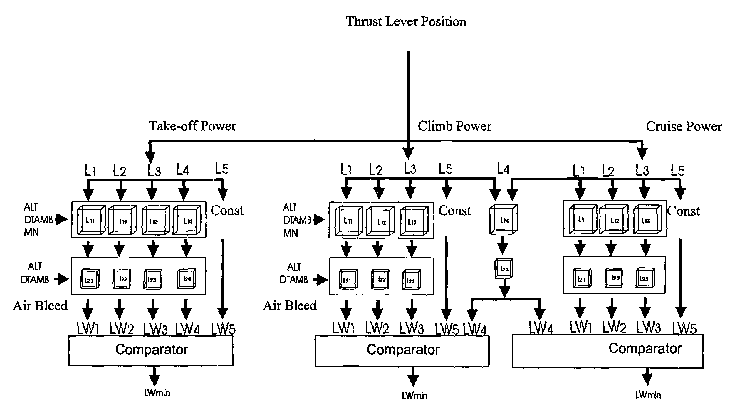
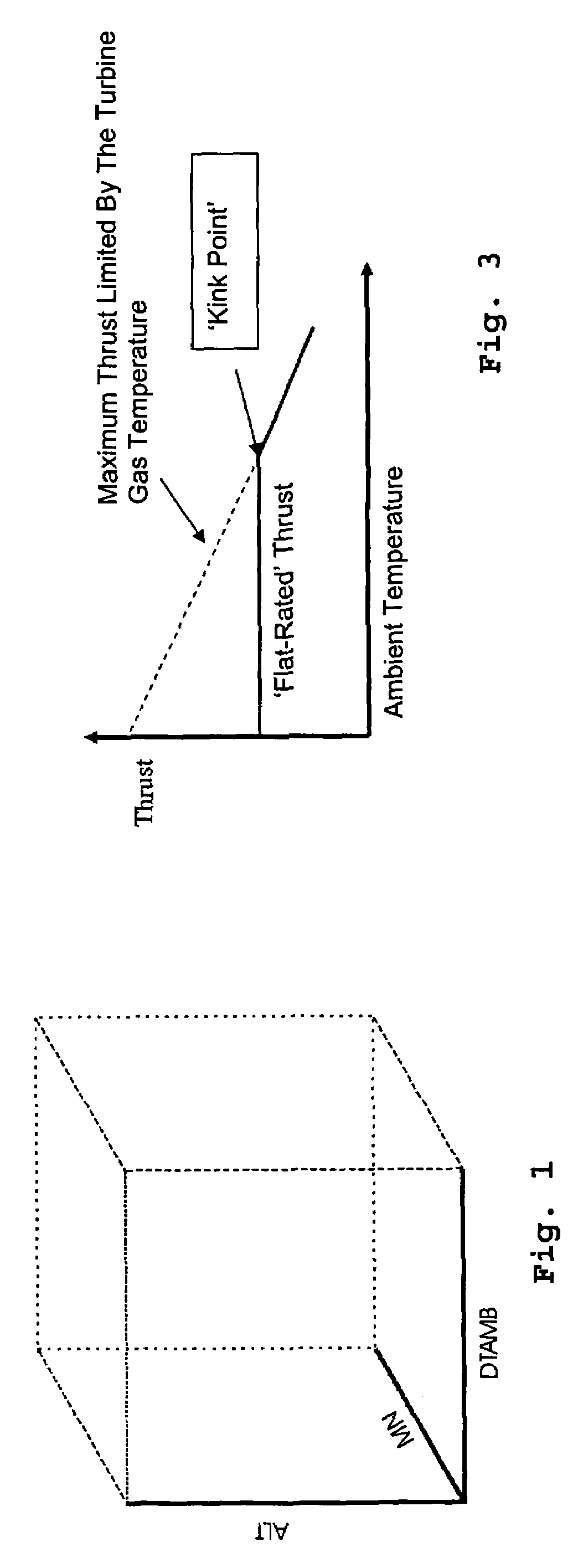
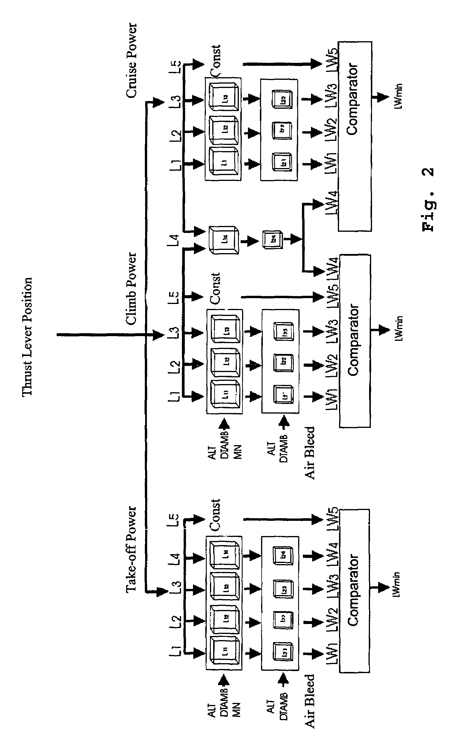
[0016]According to FIG. 2, power is controlled at the various engine ratings—take-off, climb and cruise—on the basis of the pilot's power lever setting. In the data cube illustrated in FIG. 1, a data set or data cube is shown for a certain rating for different[0017]flight altitudes (ALT), each related to a certain pressure,[0018]ambient temperatures, as a difference from the ISA temperature (DTAMB), and[0019]flight Mach numbers (MN).

[0020]As shown in FIG. 2, such three-dimensional data tables, namely the first data cubes L11 to L14, are, in the present version, deposited in the memory of the electronic engine control (EEC) for four power-limiting parameters (limiters L1 to L4) and actually, in the present embodiment, for three different engine ratings, here take-off, climb and cruise, these power-limiting parameters, which are specified for a certain altitude and which shall not be exceeded, being here[0021]a maximum turbine gas temperature (L1)[0022]a maximum high-pressure shaft sp...


PUM


Abstract

In an electronic control system, three-dimensional data sets (data cubes L11-L14) for different power-limiting engine parameters are stored at different engine ratings for setting a respective maximum engine power in relation to flight altitude (ALT), ambient temperature (DTAMB) and flight Mach number (MN) to separately calculate a maximum power corresponding to each parameter. For power reduction due to air bleed, corresponding separate data cubes (L21-L24) are stored. In a comparator, the respective smallest power reduction value is determined and, subsequently, the fuel supply is set according to that power reduction value. Under conforming boundary conditions, the same data cubes (L24) can be stored for different engine ratings. The system requires low storage capacity and low calculating effort.

Description

[0001]This application claims priority to German Patent Application DE10329252.7 filed Jun. 25, 2003, the entirety of which is incorporated by reference herein.BACKGROUND OF THE INVENTION[0002]This invention relates to an electronic engine control system for setting a max. possible power on the basis of the flight condition data stored in a data cube for various engine ratings and a variety of power-limiting thermodynamic and mechanical engine parameters.[0003]The maximum power provided by an aircraft engine without transgression of its thermal and mechanical loadability depends essentially on the respective flight condition which is adequately defined firstly by the flight altitude, secondly by the ambient temperature and thirdly by the flight Mach number. An important, power-limiting thermodynamic engine parameter for the power control of aircraft engines is the turbine gas temperature which is known to be applied such that—on the basis of a constant flight Mach number and a const...

Claims


Application Information

Patent Timeline
IPC IPC(8): G06F7/00F02C9/00F02C9/28
CPCF02C9/00F02C9/28Y02T50/671Y02T50/60
Inventor BARTEL, MATTHIAS
Owner ROLLS ROYCE DEUT LTD & CO KG
Why Eureka
Try Eureka