Adhesive particle shielding

a technology of adhesive particles and shielding, applied in the direction of colloidal chemistry, separation processes, filtration separation, etc., can solve the problems of surface defects that cannot be developed to the point of application, and can be related to each other

Active Publication Date: 2009-01-06
EUV +1
View PDF37 Cites 5 Cited by
  • Summary
  • Abstract
  • Description
  • Claims
  • Application Information

AI Technical Summary

Benefits of technology

[0007]The present invention is based in part on the recognition that strategically positioning an adhesive particle shield can significantly reduce and / or essentially eliminate contaminants typically generated in vacuum systems. The invention is particularly suited for photolithographic systems having critical surfaces, such as wafers, masks, and optics, that are sensitive particle contamination. The inventive shield can also be employed in thin film depositions, e.g., sputter or CVD, that are used to coat these critical surfaces. The shield can be designed as a portable unit to be positioned in hard-to-reach areas of a photolithography machine.
[0012]In yet another embodiment, the adhesive particle shield can incorporate cooling means to attract particles via the thermophoresis effect.

Problems solved by technology

Generally, surface defects can be related to particulate matter being deposited onto surfaces of reticles (masks) and wafer substrates during the various operations required to produce integrated circuits.
However, each of these alternative schemes has disadvantages and none has been developed to the point of application.

Method used


Image

  • Adhesive particle shielding
  • Adhesive particle shielding

Examples


Embodiment Construction

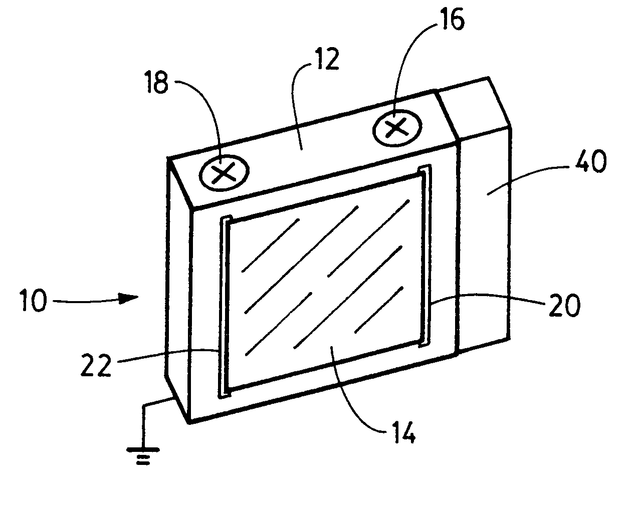
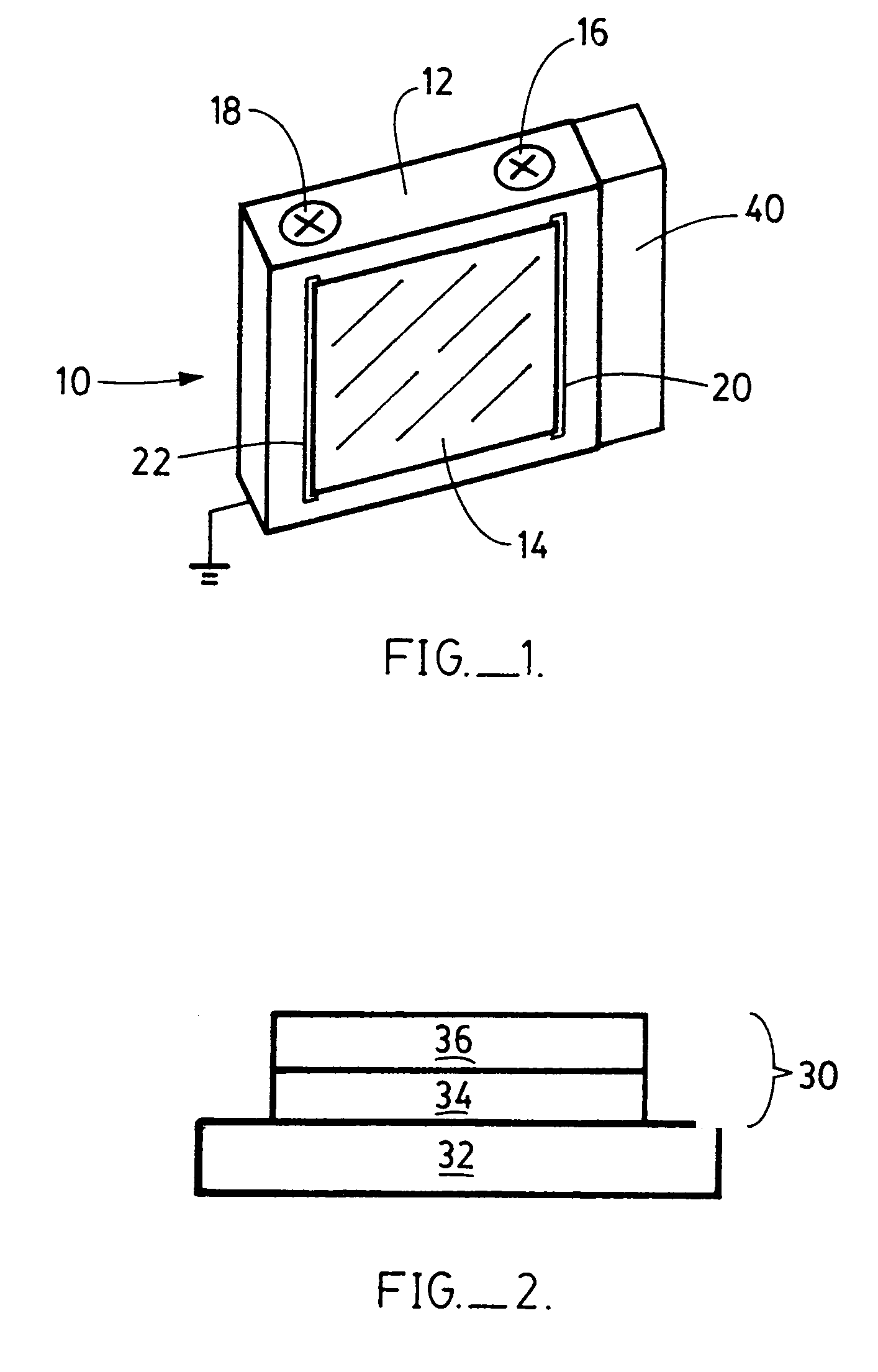
[0015]FIG. 1 illustrates one embodiment of the adhesive particle shield 10 which includes mounting panel 12 supporting adhesive film 14. The configuration and dimensions of the mounting panel are not critical, however, in one preferred embodiment, the mounting panel is sized so that it can be manually handled and maneuvered into extreme ultraviolet lithography systems such as that described in Tichenor et al. “Extreme Ultraviolet Lithography Machine” U.S. Pat. No. 6,031,598 which is incorporated herein. The mounting panel can be made of any vacuum compatible material which does not release, i.e., outgas, vapors in subatmospheric pressures. Preferred materials include, for example, stainless steel, and ceramics. For a variety of reasons including safety requirements, the mounting panel can be electrically grounded.

[0016]The adhesive film 14 can be attached to one or more sides of the mounting panel by conventional means. As further descried herein, the adhesive film typically compris...


PUM

PropertyMeasurementUnit
velocityaaaaaaaaaa
diametersaaaaaaaaaa
diametersaaaaaaaaaa

Abstract

An efficient device for capturing fast moving particles has an adhesive particle shield that includes (i) a mounting panel and (ii) a film that is attached to the mounting panel wherein the outer surface of the film has an adhesive coating disposed thereon to capture particles contacting the outer surface. The shield can be employed to maintain a substantially particle free environment such as in photolithographic systems having critical surfaces, such as wafers, masks, and optics and in the tools used to make these components, that are sensitive to particle contamination. The shield can be portable to be positioned in hard-to-reach areas of a photolithography machine. The adhesive particle shield can incorporate cooling means to attract particles via the thermophoresis effect.

Description

[0001]This invention was made with Government support under Contract No. DE-AC04-94AL85000 awarded by the U.S. Department of Energy to Sandia Corporation. The Government has certain rights to the invention.FIELD OF THE INVENTION[0002]This invention relates generally to an apparatus for preventing surface contamination by intercepting and capturing particulate matter and particularly for preventing deposition of particulate matter onto lithographic components such as reticles (masks), wafers, and other critical components during lithographic use, fabrication, inspection, repair, handling, and storage.BACKGROUND OF THE INVENTION[0003]The ability to produce high quality microelectronic devices and reduce yield losses is strongly dependent upon maintaining the surfaces substantially defect-free. This is particularly true as design rules drive integrated circuits to finer feature size. Generally, surface defects can be related to particulate matter being deposited onto surfaces of reticl...

Claims


Application Information

Patent Timeline
Patent Type & Authority Patents(United States)
IPC IPC(8): B01D45/08H01L21/00
CPCH01L21/67017H01L21/67132Y10S55/14
Inventor KLEBANOFF, LEONARD ELLIOTTRADER, DANIEL JOHNWALTON, CHRISTOPHERFOLTA, JAMES
Owner EUV
Why Eureka
Try Eureka