Electromagnetic drive device

a technology of electromagnetic drive and drive device, which is applied in the direction of magnetic bodies, operating means/releasing devices of valves, magnetic bodies, etc., can solve the problems of friction coefficient, wear of coating portion, and exposed magnetic body of stator or moving par

Active Publication Date: 2009-01-06
DENSO CORP
View PDF6 Cites 1 Cited by
  • Summary
  • Abstract
  • Description
  • Claims
  • Application Information

AI Technical Summary

Benefits of technology

[0009]The present invention has an object of providing an electromagnetic drive device which stably reduces wear between a stator and a movable member (moving part) and a change in moving force of the movable member for a long period of time.
[0011]Therefore, the concave portions in the uneven wall portion are filled with the lubricating layer portion containing the lubricating particles. Accordingly, even if a part of the lubricating layer portion is reduced due to wear, the lubricating particles filled in the concave portions in the uneven wall portion are re-supplied to a sliding portion between the stator and the movable member. As a result, the re-supplied lubricating particles always cause formation of a lubricating layer made of an extremely thin film in the sliding portion between the stator and the movable member. Accordingly, the wear between the stator and the movable member can be stably reduced for a long period of time. In addition, even if a part of the lubricating layer portion is reduced, the lubricating particles are re-supplied. Therefore, it is not required to increase the thickness of the lubricating layer portion. Accordingly, the moving force of the movable member can be stably maintained for a long period of time. Further, the lubricating particle is larger than the clearance between the adjacent convex portions of the micro concave and convex portion and smaller than the clearance between the adjacent convex portions of the uneven wall portion forming the concavity and convexity. Therefore, the lubricating particles are stored in the concave portions of the uneven wall portion, while not entering into the concave portions of the micro concave and convex portion. Therefore, only a carrier portion retaining the lubricating particles enters into the concave portions of the micro concave and convex portion. As a result, a contact area between the magnetic body and the lubricating layer portion increases. Accordingly, adherence between the magnetic body and the lubricating layer portion can improve.
[0013]Accordingly, the second aspect of the present invention has the advantages similar to the first aspect of the present invention and further, since the nonmagnetic plated layer portion is formed between the stator and the movable member, a magnetic force perpendicular to the axis can be reduced. Accordingly, the wear between the stator and the movable member can be stably reduced for a long period of time.
[0015]Therefore, the concave portions in the uneven wall portion are filled with the lubricating layer portion containing the lubricating particles. Accordingly, even if a part of the lubricating layer portion is reduced due to wear, the lubricating particles filled in the concave portions in the uneven wall portion are re-supplied to a sliding portion between the stator and the movable member. As a result, the re-supplied lubricating particles always cause formation of a lubricating layer made of an extremely thin film in the sliding portion between the stator and the movable member. Accordingly, the wear between the stator and the movable member can be stably reduced for a long period of time.
[0016]For example, the lubricating layer portion may include the lubricating particles which are equal to at least 40% in mass of the entire lubricating layer portion. For reducing wear of the sliding portion between the stator and the movable member, the density of the lubricating particles is preferably the higher. On the other hand, as the density of the lubricating particles becomes higher, it is more difficult to form the lubricating layer portion. Therefore, the density of the lubricating particles is set 40% in mass as the lower limit. Further, the upper limit of the density of the lubricating particles varies with a material, a shape or a size of the surface of the stator or the movable member forming the lubricating layer portion. Accordingly, the upper limit of the density of the lubricating particles may be set possibly high in such a manner as to form the lubricating layer portion.

Problems solved by technology

However, in a case of forming the coating portion at the stator or the moving part, relative movement between the stator and the moving part for a long period of time causes wear of the coating portion.
Further, when the coating portion disappears due to the wear development, the magnetic body of the stator or the moving part is exposed.
Therefore, disappearance of the coating portion rapidly increases a friction coefficient, which invites to the wear of the stator and the moving part.
As a result, deterioration in controllability or interruption of the movement of the moving part may be caused.
In addition, in a case of increasing the thickness of the coating portion for extending a lifetime of the coating portion, a clearance between the stator and the moving part is enlarged due to development of the wear of the coating portion.

Method used


Image

  • Electromagnetic drive device
  • Electromagnetic drive device
  • Electromagnetic drive device

Examples


Embodiment Construction

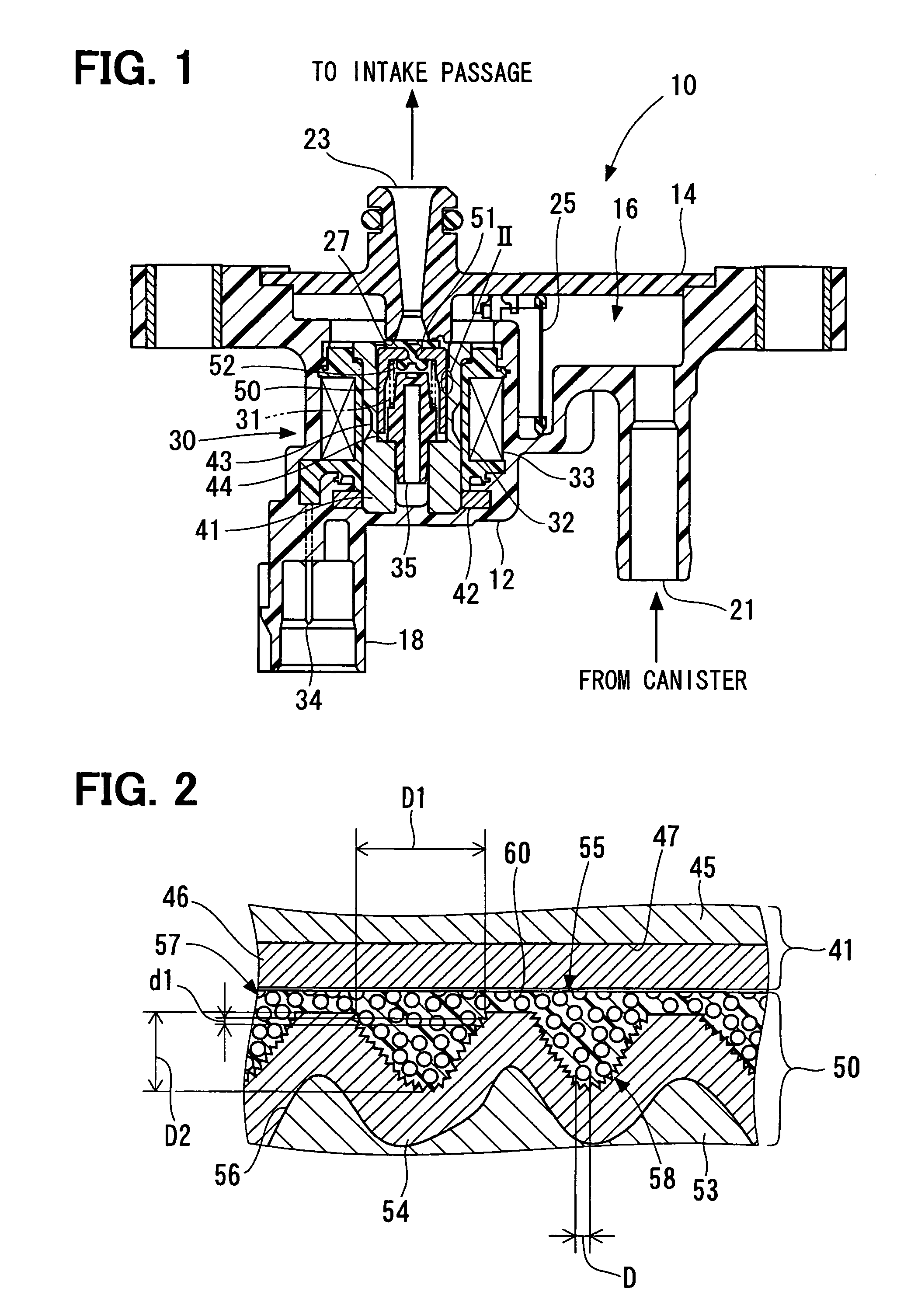
[0021]An embodiment will be hereinafter explained with reference to the accompanying drawings. In this embodiment, an electromagnetic drive device is typically used for a purge valve. A purge valve 10 shown in FIG. 1 is used for an evaporative fuel treating device for treating fuel evaporated in a fuel tank (not shown), for example. The purge valve 10 is located in a purge pipe connecting a canister (not shown) to an intake passage. The purge valve 10 controls a quantity of air containing fuel vapor flowing in the purge pipe.

[0022]The purge valve 10 is provided with a body 12 and a cover 14 constituting a housing. The body 12 and the cover 14 are constructed integrally by welding, for example, and are provided with a purge passage 16 therein.

[0023]The body 12 is formed of a resin and includes an inlet port 21. The inlet port 12 is connected to a purge port of a canister (not shown). The cover 14, as similar to the body 12, is formed of a resin and includes an outlet port 23. The out...


PUM


Abstract

A moving core includes a magnetic body having a rough face-shaped wall portion at a side facing a stationary core, a plated layer portion provided on the magnetic body and including a micro concave and convex portion on the surface layer of the plated layer portion, and a lubricating layer portion provided so as to cover the plated layer portion to store lubricating particles in the concave portions of the plated layer portion. A clearance between adjacent convex portions of the micro concave and convex portion is smaller than a clearance between adjacent convex portions of concavity and convexity of the plated layer portion. The lubricating particle is larger than the clearance between the adjacent convex portions of the micro concave and convex portion and smaller than the clearance between adjacent convex portions of the plated layer portion.

Description

CROSS-REFERENCE TO RELATED APPLICATION[0001]This application is based on Japanese Patent Applications No. 2005-197118 filed on Jul. 6, 2005, and No. 2006-120697 filed on Apr. 25, 2006, the disclosure of which is incorporated herein by reference in its entirety.BACKGROUND OF THE INVENTION[0002]1. Field of the Invention[0003]The present invention relates to an electromagnetic drive device in which a moving part supported to a stator moves at an inner side of the stator.[0004]2. Description of the Related Art[0005]There is known an electromagnetic drive device which directly supports a moving part at an inner peripheral side of a stator for reduction in the number of components and simplification the structure. In such an electromagnetic drive device, a coating portion is provided in at least one of the stator and the moving part for reducing hysteresis of the moving part at the time of power supply or non-power supply to a coil (refer to JP-A-2001-263524 or JP-A-2002-222710 correspond...

Claims


Application Information

Patent Timeline
Patent Type & Authority Patents(United States)
IPC IPC(8): H02K5/16
CPCF16K31/0658F16K31/0675H01F7/081H01F7/1607H01F7/128H01F7/13
Inventor OKUDA, HIDEKISEKO, NAOHITOKAWABATA, SANEMASA
Owner DENSO CORP
Why Eureka
Try Eureka