System and method for oscillator noise cancellation

a technology of oscillator and noise cancellation, applied in the field of electronic circuits, can solve problems such as maintaining the frequency stability of high frequency

Inactive Publication Date: 2009-01-06
SENSOR PLATFORMS
View PDF1 Cites 30 Cited by
  • Summary
  • Abstract
  • Description
  • Claims
  • Application Information

AI Technical Summary

Benefits of technology

[0011]In general, in one aspect, the invention relates to a method for reducing effects from a noise source of an electronic circuit having a first comparator and a second comparator, each of the first comparator and the second comparator having a corresponding offset voltage and operatively coupled to a corresponding sampling capacitor, the method comprising operating the electronic circuit at an operating frequency substantially higher than a frequency of the noise source, generating a reset period and a non-reset period of the electronic circuit, storing a sampled offset voltage associated with at least one selected from a group consisting of the first comparator and the second comparator in the corresponding sampling capacitor during the reset period, and subtracting the sampled offset voltage subtracted from the corresponding input offset voltage during the non-reset period.

Problems solved by technology

The longer the time duration to be counted the lower in frequency is the 1 / F noise and the more problematic it is in maintaining the frequency stability of the high frequency oscillator over that long time duration.
1 / F noise is also problematic for measuring short durations of the low frequency oscillator in that repeated measurements taken with long intervals between measurements (e.g., seconds or days) will cause non-repeatable results.

Method used


Image

  • System and method for oscillator noise cancellation
  • System and method for oscillator noise cancellation
  • System and method for oscillator noise cancellation

Examples


Embodiment Construction

[0021]Specific embodiments of the invention will now be described in detail with reference to the accompanying figures. Like elements in the various figures are denoted by like reference numerals for consistency.

[0022]In the following detailed description of embodiments of the invention, numerous specific details are set forth in order to provide a more thorough understanding of the invention. In other instances, well-known features have not been described in detail to avoid obscuring the invention.

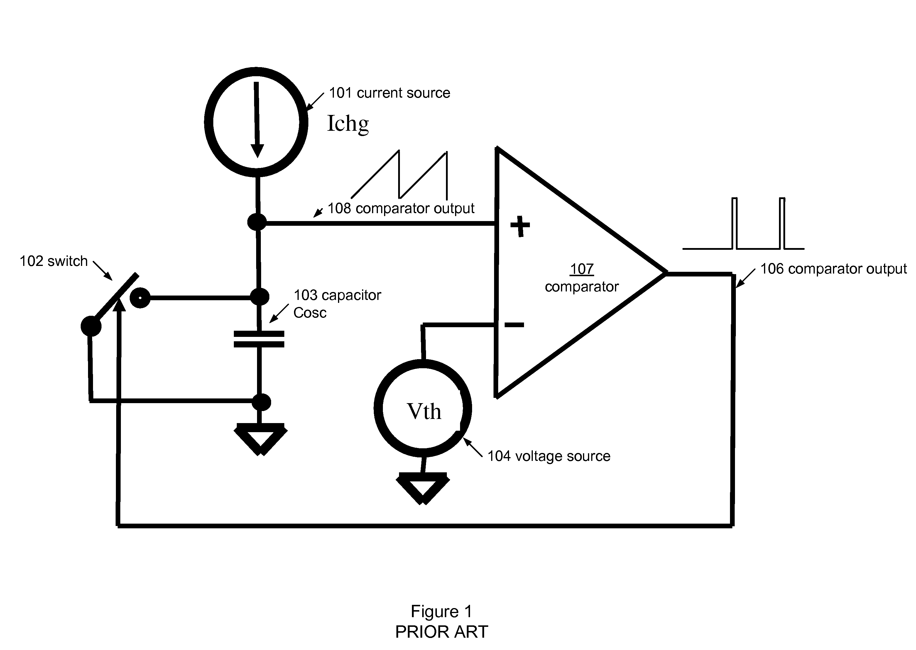
[0023]The oscillator shown in FIG. 1, as is known within the art, is implemented using a current source (101), a switch (102), a capacitor (103), a voltage source (104), and a comparator (107). The switch may be implemented using a transistor fabricated using various technologies well known in the art, or any other suitable devices. The voltage source may be implemented as a current passing through a resistor, or other suitable circuit configurations. The oscillator shown in FIG. 1 produc...


PUM


Abstract

The invention relates to an electronic circuit comprising a first comparator having a first input offset voltage, wherein the first comparator is operatively coupled to a first sampling capacitor, a second comparator having a second input offset voltage, wherein the second comparator is operatively coupled to a second sampling capacitor, and a control circuit operatively coupled to the first comparator and the second comparator for generating alternate cycles having a first phase and a second phase, wherein a first sampled offset voltage is stored in the first sampling capacitor during the first phase of the alternate cycles, wherein the first sampled offset voltage is subtracted from the first input offset voltage during the second phase of the alternate cycles, wherein a second sampled offset voltage is stored in the second sampling capacitor during the second phase of the alternate cycles, and wherein the second sampled offset voltage is subtracted from the second input offset voltage during the first phase of the alternate cycles.

Description

BACKGROUND OF THE INVENTION[0001]1. Field of the Invention[0002]The present invention relates to an electronic circuit. More particularly, the invention relates to techniques for noise cancellation in an electronic circuit.[0003]2. Background of the Related Art[0004]There are many applications that benefit from a stable low jitter oscillator. For example, in an application which uses a high frequency clock to measure the periods of a low frequency asynchronous oscillator, the stability of the high frequency clock directly impacts the final result.[0005]One means to generate a high frequency oscillator is shown in FIG. 1. This circuit operates by charging a capacitor (103) with a constant current source Ichg (101) into a timing capacitor Cosc (103) (note: assume the comparator output is LOW to start). When the voltage across the capacitor (103) exceeds the threshold voltage Vth (104), the output (106) of the comparator (107) goes high forcing switch (102) to close. Closing switch (10...

Claims


Application Information

Patent Timeline
Patent Type & Authority Patents(United States)
IPC IPC(8): H03K3/02H03L1/00
CPCH03K3/017H03K3/0231
Inventor WILE, DONHUFFMAN, DAVE
Owner SENSOR PLATFORMS
Why Eureka
Try Eureka