Playback method for an after-recording operation

a playback method and after-recording technology, applied in the field of information recording medium, can solve the problems of inability to act as a random access device in the practical use of the tape, insufficient capacity of dvd-ram having a large capacity of several gb, and inability to operate the decoder in some cases normally, so as to achieve the effect of easy determination

Inactive Publication Date: 2009-01-06
PANASONIC CORP
View PDF17 Cites 14 Cited by
  • Summary
  • Abstract
  • Description
  • Claims
  • Application Information

AI Technical Summary

Benefits of technology

[0041]This invention is directed to provide information recording medium which actualize easy determination of a possibility of after-recordin

Problems solved by technology

Significant problems in the future are how to record AV data including video data using an optical disc intended to have an increase in a capacity, and how to implement performance greatly exceeding a conventional AV apparatus and new functions.
Accordingly, the tape cannot act as a random access device in respect of practical use.
Even a DVD-RAM having a large capacity of several GBs does not always have a sufficient capacity for exactly recording non-compressed digital AV data.
The biggest problem to an after-recording operation in the DVD recorder is caused by an MPEG stream which is AV

Method used


Image

  • Playback method for an after-recording operation
  • Playback method for an after-recording operation
  • Playback method for an after-recording operation

Examples


first embodiment

(Logical Structure on DVD-RAM)

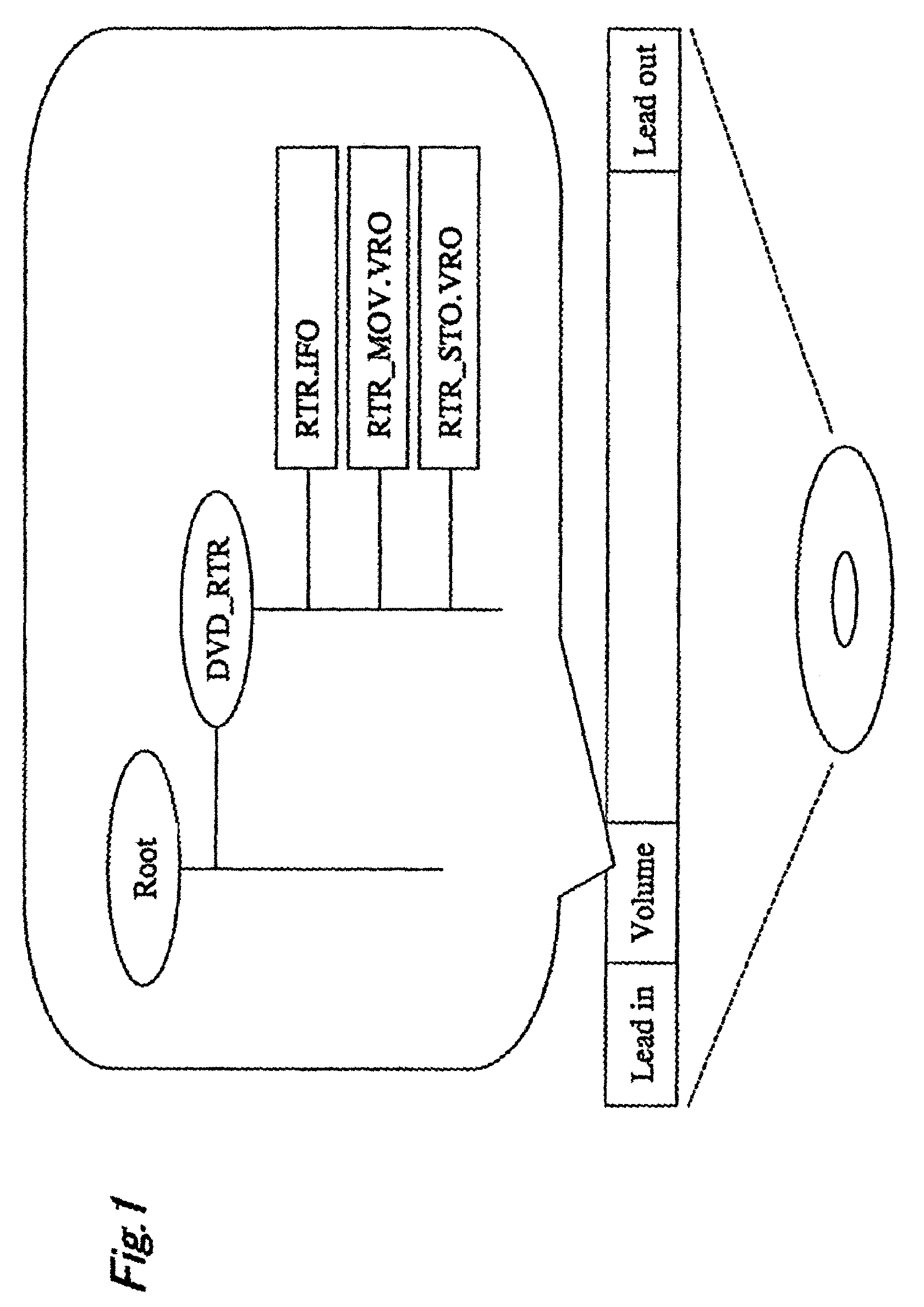
[0104]First of all, the logical structure on the DVD-RAM will be described with reference to FIGS. 41A and 41B. FIG. 41A shows a data structure on a disc seen through a file system, and FIG. 41B shows a physical sector address on a disc.

[0105]The head portion of the physical sector address has a lead-in region which stores a reference signal necessary for stabilizing a servo, an identification signal with other media and the like. A data region is provided following the lead-in region. In this portion, logically effective data are recorded. Finally, a lead-out region is provided and stores the same reference signal as in the lead-in region and the like. A management information for the file system which is referred to as a volume information is recorded on the head of the data region. Since the file system is not directly related to the contents of the present invention, the description of it will be omitted.

[0106]Through the file system, the data in th...

second embodiment

[0186]It has been possible to implement the after-recording operation which is hard to perform in the DVD and the DVD recorder in the first embodiment. However, the DVD and the DVD recorder further have the following problem.

[0187]Different from the conventional tape media, the DVD can carry out recording in various audio stream formats. This causes the after-recording operation in the DVD recorder to be hard to perform.

[0188]Concretely, the audio stream which can be recorded in the DVD has three kinds of formats of AC-3, MPEG audio and linear PCM. Moreover, there are various modes such as recording channel numbers, a recording bit rate and the like in individual formats.

[0189]On the other hand, a general audio encoder rarely can operate with all encode modes, channel numbers and bit rates, and can operate with only a mode suitable for each merchandise target. In other words, when the after-recording operation is applied to the disc on which data have been recorded by the other DVD ...


PUM


Abstract

The invention provides an information recording medium, such as an optical disk, having a large capacity and being capable of performing read/write operations at high speeds. The recording medium includes an audio stream prepared for after-recording data, and a audio attribute information having a bit rate information to the recorded audio stream as a management information. A recorder according to the invention has a check unit for checking, in advance, the possibility of after-recording operation of the recorder to the audio stream to be after-recorded with reference to the bit rate information of the audio attribute information.

Description

[0001]This is a Divisional Application of U.S. application Ser. No. 09 / 672,959, filed Sep. 29, 2000, now U.S. Pat. No. 6,665,491 which is a Divisional Application of U.S. application Ser. No. 09 / 504,938, filed Feb. 16, 2000 now U.S. Pat. No. 6,374,037.BACKGROUND OF THE INVENTION[0002]1. Field of the Invention[0003]The present invention relates to an information recording medium like an optical disc which has large capacity and to / from which data are written / read in high speed, and more particularly to a recording medium which can perform after-recording, an apparatus and a method for recording thereto.[0004]2. Related Art[0005]In the field of a writable optical disc having an upper bound of approximately 650 MB, a phase change type disc DVD-RAM having a capacity of several GB has appeared. Moreover, in addition to the practical use of MPEG (MPEG2) which is the coding standard of digital AV data, the DVD-RAM has been expected as recording and reproducing media in the AV field as well...

Claims


Application Information

Patent Timeline
IPC IPC(8): H04N7/00H04N5/00H04N5/91H04N7/26G11B20/10G11B20/12G11B27/00G11B27/02G11B27/034G11B27/036G11B27/10G11B27/30G11B27/32G11B27/34G11B27/36H04N5/05H04N5/85H04N5/92H04N9/804H04N9/806
CPCG11B20/10527G11B27/036G11B27/105G11B27/329G11B27/34G11B27/36H04N9/8042G11B27/034G11B27/3027G11B2020/10592G11B2220/216G11B2220/2562G11B2220/2575H04N5/05H04N5/85H04N9/8063G11B20/1217G11B2020/1267G11B2220/2537
Inventor OKADA, TOMOYUKIMURASE, KAORUSUGIMOTO, NORIKOTSUGA, KAZUHIRO
Owner PANASONIC CORP
Why Eureka
Try Eureka