
Slow-dynamic load balancing method

a load balancing and slow-dynamic technology, applied in the field of data processing, can solve the problems of adversely affecting the overall performance of the system, unsatisfactory load balancing methods known in the art, and inability to replicate specific information for all clients on the different servers, so as to reduce the switching of clients

Inactive Publication Date: 2009-01-06
IBM CORP
View PDF31 Cites 52 Cited by
  • Summary
  • Abstract
  • Description
  • Claims
  • Application Information

AI Technical Summary

Benefits of technology

The present invention provides a load balancing method for a data processing system with a distributed architecture including multiple servers and clients. The method aims to reduce the switching of clients between different servers, reach a steady condition where specific information of clients is not continuously moved across the system, and distribute clients across servers without impairing overall system performance. The method includes steps of associating clients with preferred servers, detecting workload and response time of servers, selecting eligible servers based on workload and response time, calculating performance difference between preferred and eligible servers, and switching preferred server to eligible server when a predefined threshold is reached. The invention also provides a computer program for performing the method and computer programs for clients and servers.

Problems solved by technology

An additional problem arises when information specific for each client must be stored on the servers (such as in a licensing management application).
In this case, when the number of clients is very high (for example, more than 100,000), it is not feasible to replicate the specific information for all the clients on the different servers.
However, in these environments the load balancing methods known in the art are not completely satisfactory.
These operations adversely affect the overall performance of the system, and can defeat the advantages provided by the load balancing method.

Method used


Image

  • Slow-dynamic load balancing method
  • Slow-dynamic load balancing method
  • Slow-dynamic load balancing method

Examples


Embodiment Construction

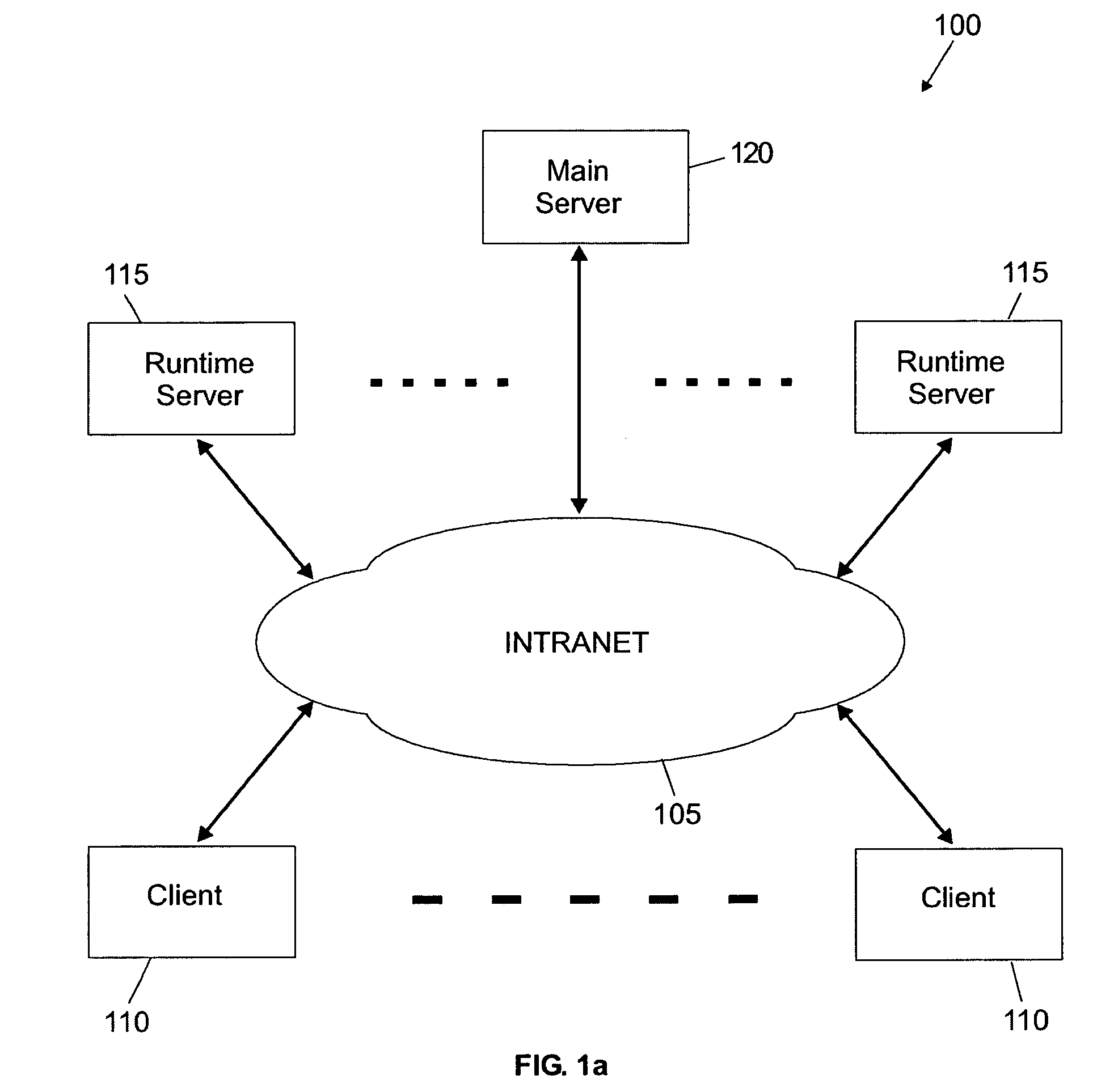
[0020]With reference in particular to FIG. 1a, a data processing system 100 with a distributed architecture is shown. The system 100 is based on a communication network 105 (for example, an intranet). The system 100 includes a large number of clients 110 (for example, more than 100,000); typically, the clients 110 consist of laptop computers, which can move in the system 100 freely (connecting to the network 105 from different access points around the world). Each client 110 relies on resources managed by multiple runtime servers 115 (generally consisting of powerful computers); for example, the system 100 includes some tens of runtime servers 115, which are distributed across different sites in several countries. A main server 120 controls the runtime servers 115 from a central point of the system 100.

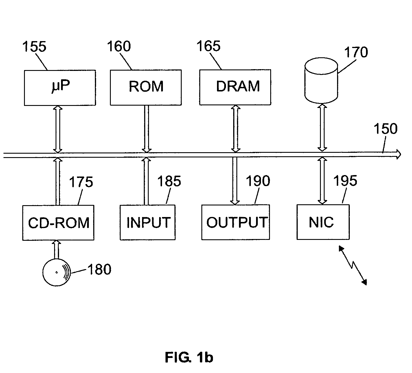
[0021]Considering now FIG. 1b, a schematic block diagram of a generic computer of the system 100 (client, runtime server or main server) is shown. The computer is formed by several un...


PUM


Abstract

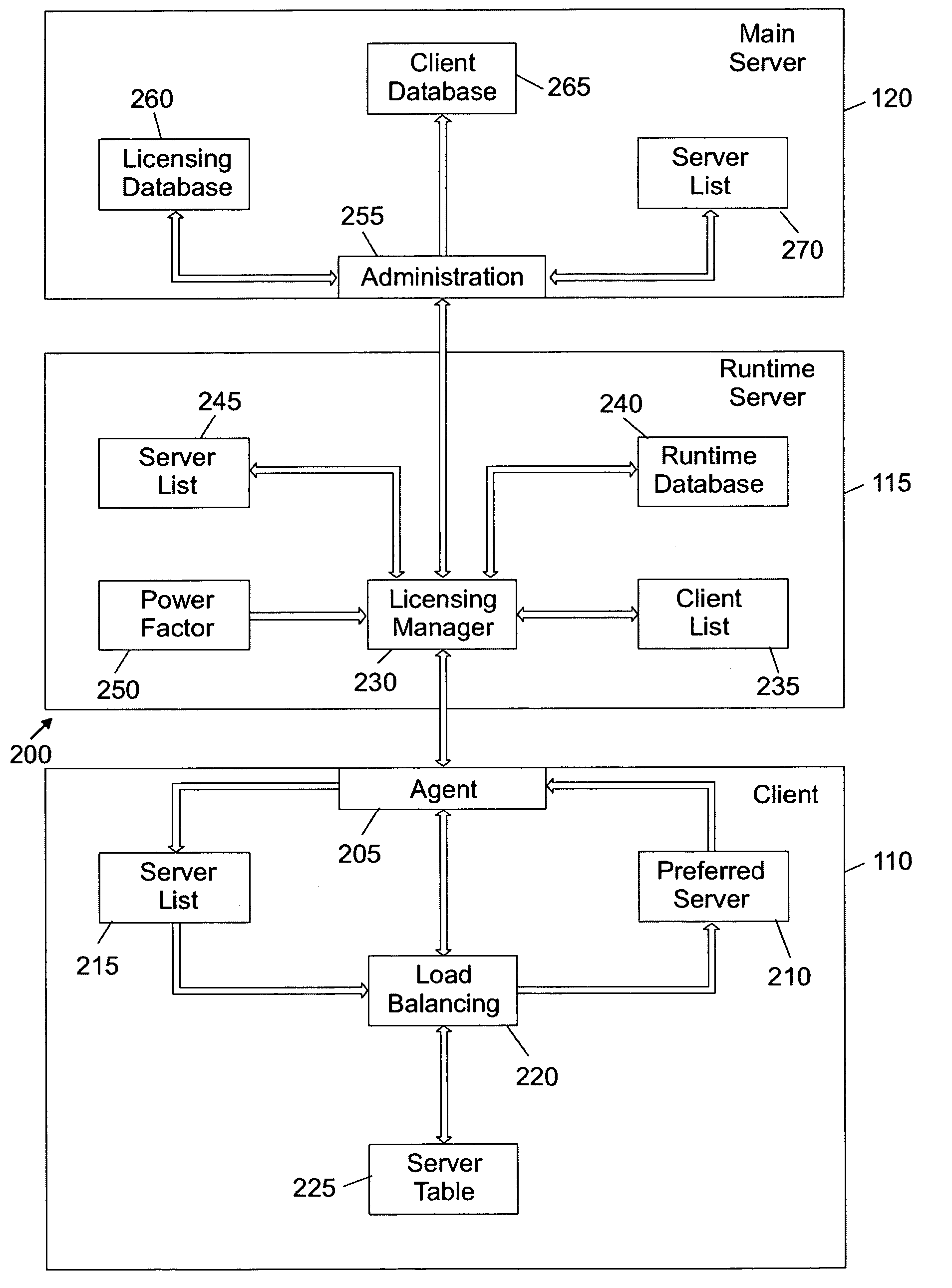
A load balancing method and a corresponding system are proposed. The load balancing method is used in environments (e.g., implementing a licensing management application) wherein each client is associated with a preferred server storing specific information for the client. Each client periodically detects a workload and a response time of all the servers. The client selects a subset of nearest servers (according to their response times). The server in that subset with the lowest workload is set as an eligible server. Whenever a ratio between the workload of the preferred server and the workload of the eligible server exceeds a predefined threshold value (e.g., 1.1), the client switches to the eligible server (transferring the corresponding specific information). The method of the invention exhibits a slow dynamic, and tends to reach a steady condition (wherein the specific information of the clients is not continuously moved across the system).

Description

BACKGROUND OF THE INVENTION[0001]1. Field of the Invention[0002]The present invention relates to the data processing field, and more specifically to a load balancing method and a corresponding system.[0003]2. Description of the Related Art[0004]Load balancing methods are commonly used in data processing systems with a distributed architecture, wherein several clients rely on resources managed by multiple servers. The object of the load balancing methods is that of distributing the requests coming from the clients across the servers, such that overall performance of the system is increased.[0005]A typical example is that of a server farm, which consists of a cluster of mirrored servers; the mirrored servers store identical information and provide the same services to the clients. The clients access the server farm through a router, which is the only unit visible to the outside. Whenever a client attempts to contact the server farm, the corresponding request is received by the router,...

Claims


Application Information

Patent Timeline
Patent Type & Authority Patents(United States)
IPC IPC(8): G06F15/16H04L29/06H04L29/08
CPCH04L67/1008H04L67/1002H04L67/1012H04L67/1021H04L67/1001
Inventor DI GIULIO, DOMENICOPORTALURI, BRUNOROSSI, RICARDO
Owner IBM CORP
Learn More