Dynamic bushing for medical device tubing

a technology for medical devices and bushings, which is applied in the direction of sliding contact bearings, rigid support of bearings, manufacturing tools, etc., can solve the problems of difficult and time-consuming use and maintenance, and improve the cutting accuracy, so as to achieve the effect of highly accurate centering function and minimal fluid loss

Inactive Publication Date: 2009-01-13
BOSTON SCI SCIMED INC
View PDF37 Cites 38 Cited by
  • Summary
  • Abstract
  • Description
  • Claims
  • Application Information

AI Technical Summary

Benefits of technology

[0016]In at least one embodiment the dynamic bushing comprises a hydraulic chamber into which at least a portion of the tube is guided. Fluid is injected into the chamber from one or more injection ports. A gland plate is positioned adjacent to the ends of the chamber in order to regulate pressure and limit release of fluid from the chamber. When fluid is injected into the chamber when a, tube is positioned therein, the chamber acts as a hydraulic bearing as long as the fluid supplied to the chamber exceeds the fluid lost through the gland plates. In some embodiments one or both gland plates define a labyrinth to create pressure decreasing zones to minimize loss of fluid from the chamber. In use the chamber provides a uniform pressure equally to all surfaces of the tube thus providing a highly accurate centering function.

Problems solved by technology

However, if the tube has any outer diameter variations the tube will be capable of slight movement within the bushing and potentially move in and out of focus of the laser resulting in improper cutting of the tube.
Current bushing designs are very operator dependent and do not allow for any tubing variability and are thus difficult and time consuming to use and maintain.

Method used


Image

  • Dynamic bushing for medical device tubing
  • Dynamic bushing for medical device tubing
  • Dynamic bushing for medical device tubing

Examples


Embodiment Construction

[0032]While this invention may be embodied in many different forms, there are described in detail herein specific preferred embodiments of the invention. This description is an exemplification of the principles of the invention and is not intended to limit the invention to the particular embodiments illustrated.

[0033]For the purposes of this disclosure, like reference numerals in the figures shall refer to like features unless otherwise indicated.

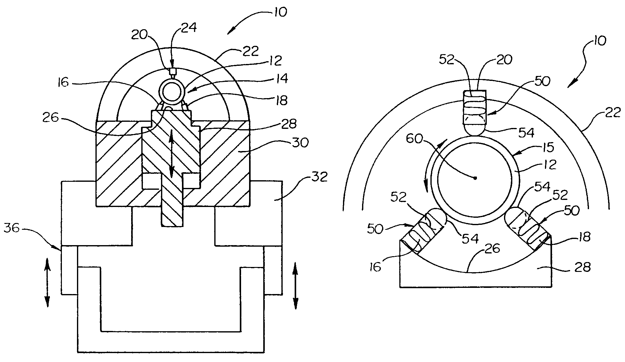
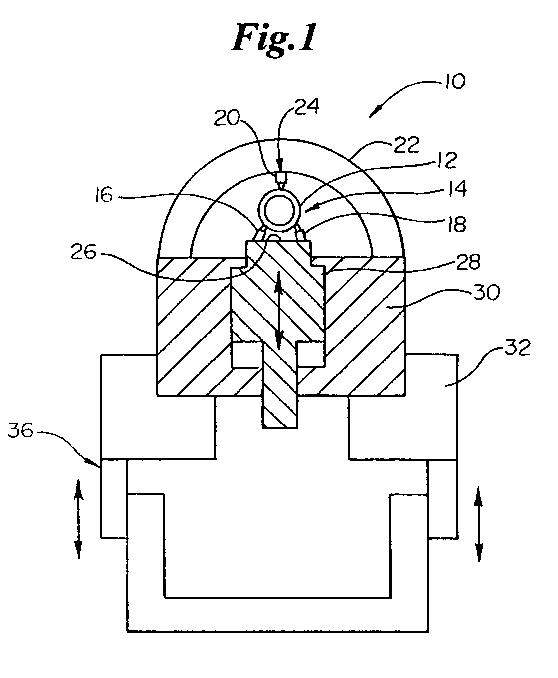
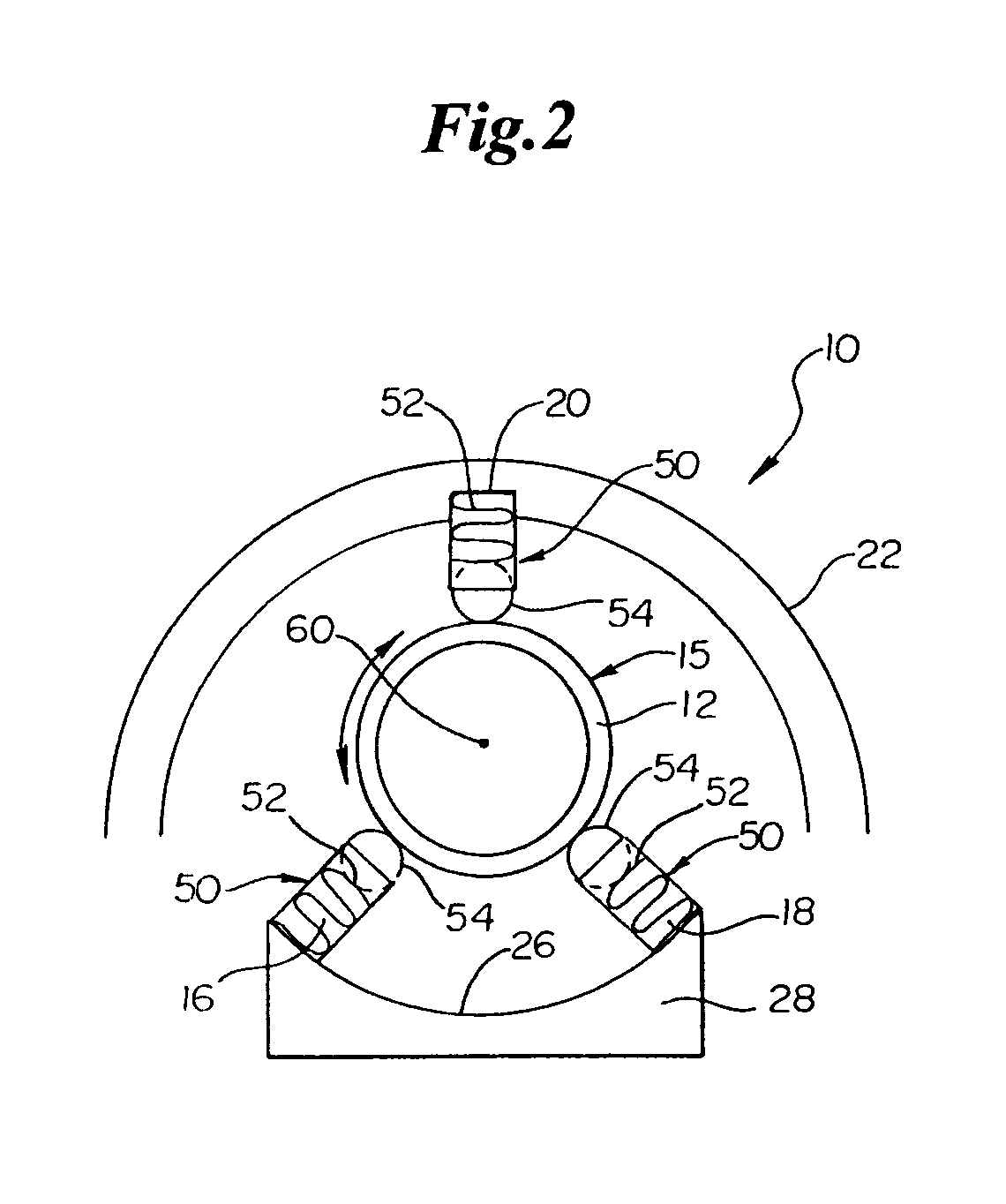
[0034]As indicated above the present invention is directed to a variety of embodiments. In at least one embodiment, shown in FIG. 1, the invention is directed to a dynamic bushing assembly (assembly), indicated generally at 10, for constraining the tube 12 when an end of the tube 12 is engaged to a tubular member cutting system or rotary assembly 200, such as the example shown in FIG. 11, for use in processing the tube into a stent or other device.

[0035]In the embodiment shown in FIG. 1, a portion of the tube 12 is passed through and positi...


PUM

PropertyMeasurementUnit
angleaaaaaaaaaa
angleaaaaaaaaaa
angleaaaaaaaaaa

Abstract

A dynamic bushing and / or gripper mechanism comprises an apparatus for retaining a tubular member in a position during processing so that the tube does not move transverse to the longitudinal axis of the bushing, but wherein the tube may be rotated within the confines of the bushing and / or in the case of the gripper mechanism the tube may be moved longitudinally within the confines of the gripper.

Description

CROSS-REFERENCE TO RELATED APPLICATIONS[0001]Not ApplicableSTATEMENT REGARDING FEDERALLY SPONSORED RESEARCH[0002]Not ApplicableBACKGROUND OF THE INVENTION[0003]A stent is a radially expandable endoprosthesis which is adapted to be implanted in a body lumen. Stents are typically used in the treatment of atherosclerotic stenosis in blood vessels and the like to reinforce body vessels and to prevent restenosis following angioplasty in the vascular system. They have also been implanted in urinary tracts, bile ducts and other bodily lumen. They may be self-expanding or expanded by an internal radial force, such as when mounted on a balloon.[0004]Delivery and implantation of a stent is accomplished by disposing the stent about a distal portion of the catheter, percutaneously inserting the distal portion of the catheter in a bodily vessel, advancing the catheter in the bodily lumen to a desired location, expanding the stent and removing the catheter from the lumen. In the case of a balloon...

Claims


Application Information

Patent Timeline
Patent Type & Authority Patents(United States)
IPC IPC(8): F16C13/00F16C17/06F16C35/06F16C43/04A61B17/00A61F2/82F16C13/04F16C29/04F16C31/04
CPCF16C13/04F16C29/04F16C31/04B23K26/0823B23K26/38A61F2/82B23K2201/06B23K2101/06
Inventor SHEDLOV, MATTHEWMERDAN, KENNETHBOODRY, JEFFREY P.LUNDQUIST, LUKE W.HITCHCOCK, JAMES K.FAUCHER, JAMES M.
Owner BOSTON SCI SCIMED INC
Why Eureka
Try Eureka