Distraction screw for skeletal surgery and method of use

a technology of distraction screws and skeletal surgery, which is applied in the field of skeletal plating systems, can solve the problems of increasing the operative risk of the second procedure for the patient, affecting the proper placement of the distraction screw, and affecting the proper alignment of the plate along the anatomically desired plane, so as to facilitate the proper placement and enhance the functional capability of the distraction screw

Active Publication Date: 2009-01-13
ABDOU M SAMY
View PDF106 Cites 158 Cited by
  • Summary
  • Abstract
  • Description
  • Claims
  • Application Information

AI Technical Summary

Benefits of technology

[0007]The present invention is one of an improved distraction screw and a method for its use. The design substantially enhances the functional capability of distraction screws used in the surgical reconstruction of mammalian bones. In this invention, the multi-segmental distraction screw comprises an implantable distal segment and a detachably secured proximal segment. The distal segment includes a head portion and a threaded shank portion. The proximal segment is represented as an elongated body having an internal bore that extends through its length. A deployable member is disposed within the proximal segment, which is extendable beyond the distal end of the internal bore to engage and secure the distal segment, thus forming a unitary distraction screw. Once assembled, the screw is used to realign and distract the bones during surgical reconstruction of a degenerated skeletal segment. Upon completion of that work, the proximal and distal segments are disengaged leaving the latter attached to bone. Securely affixed, the distal segment provides an additional point of anchoring and / or fixation for the skeletal plate and facilitates its proper placement. It also provides a ready mechanism for distraction screw replacement at the time of surgical revision without obligatory plate removal.

Problems solved by technology

Further, the empty holes often interfere with proper placement of the implantable screws and the associated skeletal plate, making proper alignment of the plate along the anatomically desired plane more difficult.
This is especially problematic since the plate is placed at the end of the operative procedure and the preceding surgical steps have distorted the anatomical landmarks required to ensure proper plate alignment.
The latter requires re-dissection through the scarred operative field of the initial procedure and significantly increases the operative risk of the second procedure for the patient.

Method used


Image

  • Distraction screw for skeletal surgery and method of use
  • Distraction screw for skeletal surgery and method of use
  • Distraction screw for skeletal surgery and method of use

Examples


Embodiment Construction

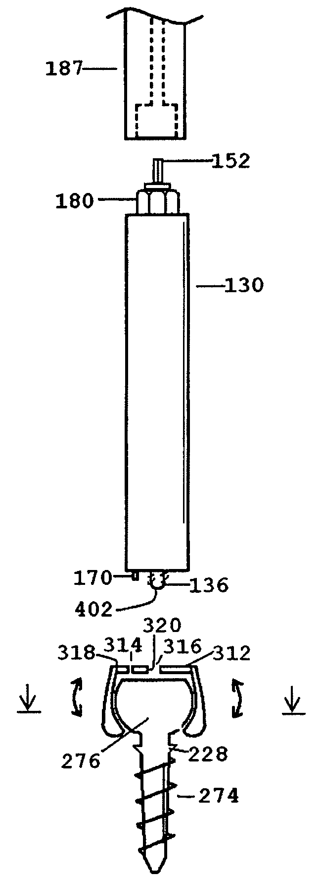
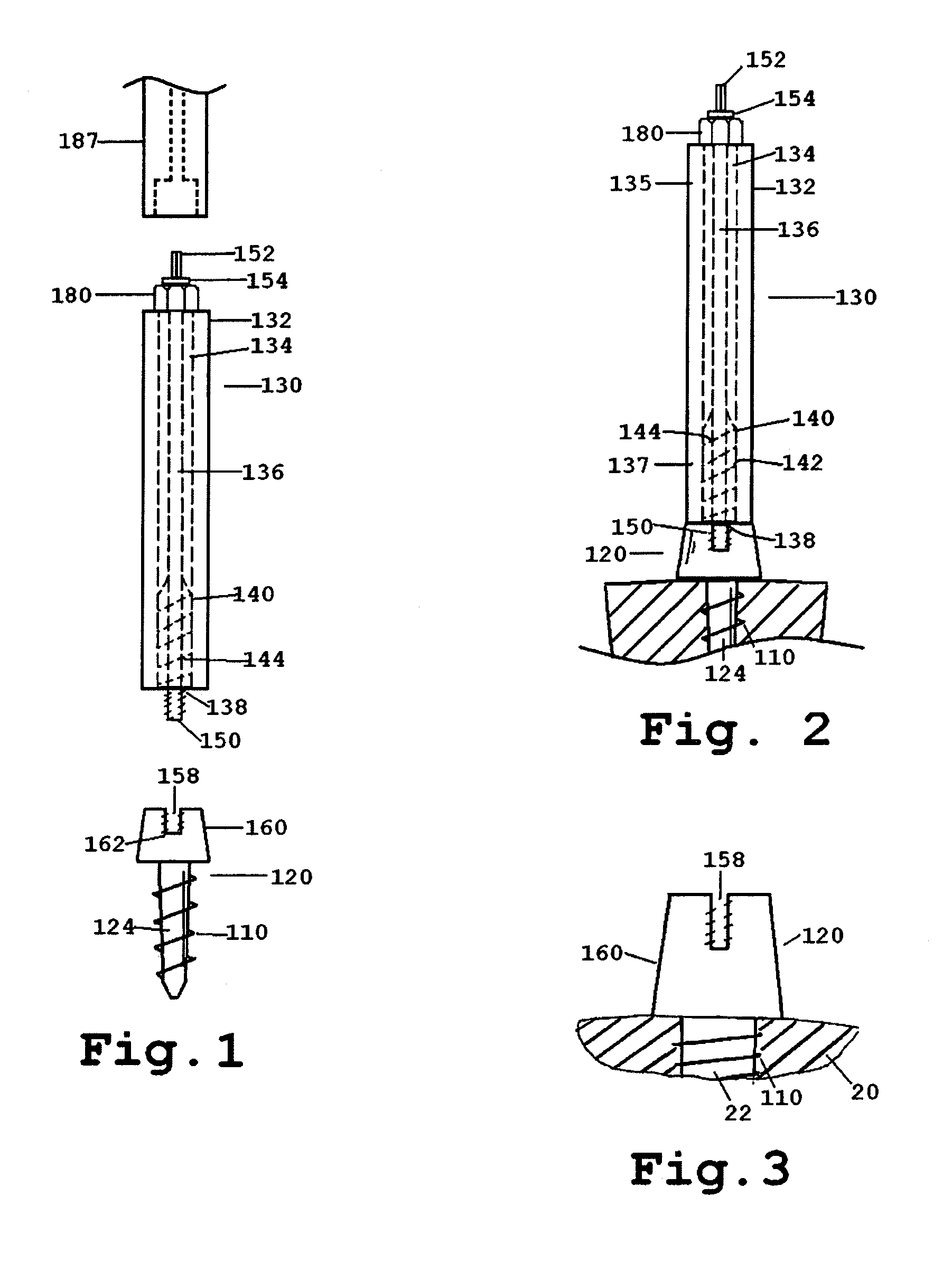
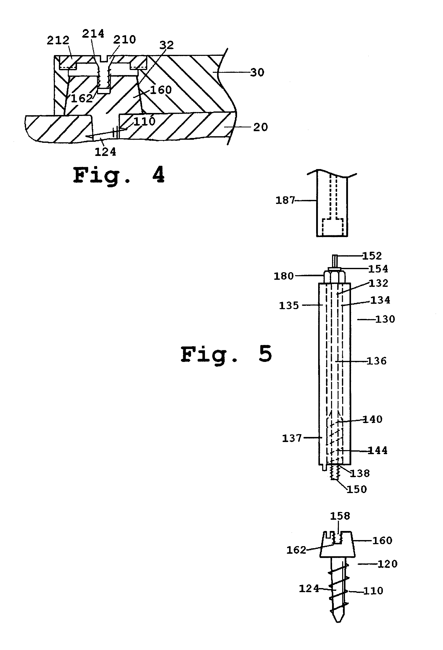
[0040]The present invention provides an improved distraction screw and a method for its use. FIG. 1 shows an embodiment of the present invention, as represented by a distraction screw 10, which comprises a distal segment 120 and a removable proximal 130 segment. The distal segment 120 is implantable on a vertebral bone as part of the surgical procedure. The distal segment 120 has a head portion 122, and a threaded shank portion 124 which can be securely fastened unto the bone structure and which may be self-tapping and / or self-drilling.

[0041]As shown in FIGS. 1 and 2, the proximal segment 130 has an elongated body 132 with an internal bore 134 extending through its length from its proximal end portion 135 to its distal end portion 137. The elongated body 132 houses a deployable member 136, which is disposed within the internal bore 134. The deployable member 136 is adapted to be retractably deployed beyond the opening 138 of the internal bore 134 at the distal end portion 137 of the...


PUM


Abstract

An improved distraction bone screw and a method for its use are described. The distraction screw is comprised of an implantable distal segment and a detachably secured proximal segment. The distal segment includes a head portion and a threaded shank portion. The proximal segment is represented as an elongated body having an internal bore that extends through its length. A deployable member is disposed within the bore, which is extendible outside the internal bore to securely couple to the distal segment. As an assembly, the distraction screw is used to affix and realign bone during surgical reconstruction. Upon completion of the surgical work, the proximal segment is removed and the distal segment is left attached to the reconstructed bone. Securely affixed, the distal segment provides an additional point of fixation for the skeletal plates that are used to preserve the bony alignment while bone healing occurs. The affixed distal segment will also provide a ready mechanism for distraction screw replacement at the time of surgical revision without obligatory plate removal. Different embodiments of the proximal segment, distal segment and the rotational locking mechanisms which inhibit the rotation of one segment relative to the other during deployment were also described. In addition, in cases where the distraction screw must be placed into the bone at an inclined angle, poly-axial heads were provided so that proper skeletal plate placement can still be accomplished.

Description

CROSS REFERENCE TO RELATED APPLICATION[0001]This application claims the benefit of the U.S. Provisional Application No. 60 / 417,776 filed Oct. 11, 2002.FIELD OF THE INVENTION[0002]The present invention relates generally to skeletal plating systems and components thereof, which can be used to adjust, align and maintain the spatial relationship(s) of adjacent bones or bony fragments during healing and fusion after surgical reconstruction of a mammalian bone structure. Such systems can comprise skeletal plates, bone screws and / or distraction screws and plate-to-screw locking mechanisms.BACKGROUND OF THE INVENTION[0003]The surgical removal of a herniated disc, whether from degenerative disease or traumatic disruption, is a common procedure in current medical practice. In the cervical spine, the procedure involves placement of a large temporary bone screw, which is also known as the distraction screw, into each of the vertebral bones above and below the diseased disc space. These screws a...

Claims


Application Information

Patent Timeline
Patent Type & Authority Patents(United States)
IPC IPC(8): A61B17/58A61BA61B17/02A61B17/70A61B17/80A61B17/86A61B17/88
CPCA61B17/7059A61B17/7082A61B17/8038A61B17/8042A61B17/861A61B17/862A61B17/8685A61B17/8877A61B17/8883A61B17/8888A61B17/8875A61B2017/0256
Inventor ABDOU, M. SAMY
Owner ABDOU M SAMY
Why Eureka
Try Eureka