Insertion device for an intraocular lens

a technology of intraocular lens and insertion device, which is applied in the field of insertion device for deformable intraocular lens, can solve the problems of inconvenient insertion the intraocular lens fails to project from the insertion end portion of the insertion tube in a desired condition, and the difficulty of controlling the insertion of the intraocular lens with consistent repeatability, etc., to achieve stable insertion speed, high skill level, and safer procedure of inserting

Active Publication Date: 2009-01-13
STAAR JAPAN
View PDF28 Cites 64 Cited by
  • Summary
  • Abstract
  • Description
  • Claims
  • Application Information

AI Technical Summary

Benefits of technology

[0019]In view of the foregoing, an object of the present invention is to provide an insertion device for a deformable intraocular lens configured such that, during an operation of inserting the intraocular lens into the eye, an intraocular lens is prevented from undergoing an unexpected rotational movement about the insertion tube axis and is intentionally caused to move rotationally in a desired direction, thereby maintaining consistent movement and stable insertion speed of the intraocular lens and its support portions and providing a safer procedure of inserting the intraocular lens into the eye.
[0020]In order to achieve the above-described object, the present invention provides an intraocular-lens insertion device for deforming a deformable intraocular lens to a smaller size and inserting the intraocular lens into an eye via an insertion tube, wherein the insertion tube has an inner wall which is shaped to cause the deformable intraocular lens to move rotationally about an insertion tube axis by a predetermined angle in the course of axial advancing movement of the lens.
[0023]By virtue of the above-described inner wall shape of the insertion tube, the folded intraocular lens can be moved rotationally by a predetermined angle about the insertion tube axis in the course of passage through the insertion tube, thereby implementing a consistent insertion operation. Accordingly, a surgical procedure for implantation of the intraocular lens does not require a particularly high level of skill.
[0024]The above-described guide portion prevents unexpected circular rotation of an intraocular lens about the insertion tube axis and intentionally causes the intraocular lens to move rotationally in a desired direction, thereby maintaining consistent movement and stable insertion speed of the intraocular lens and its support portions and providing a safer procedure of inserting the intraocular lens into the eye.

Problems solved by technology

However, in the conventional insertion device, the insertion tube is not configured to prevent rotational movement about the insertion tube axis of an intraocular lens that is contained therein in a folded condition.
As a result, the intraocular lens fails to project from the insertion end portion of the insertion tube in a desired condition.
Accordingly, difficulty arises in controlling insertion of the intraocular lens with consistent repeatability in terms of insertion orientation and insertion speed.
Therefore, a surgical procedure for implantation of the intraocular lens has required a great deal of skill.

Method used


Image

  • Insertion device for an intraocular lens
  • Insertion device for an intraocular lens
  • Insertion device for an intraocular lens

Examples


first embodiment

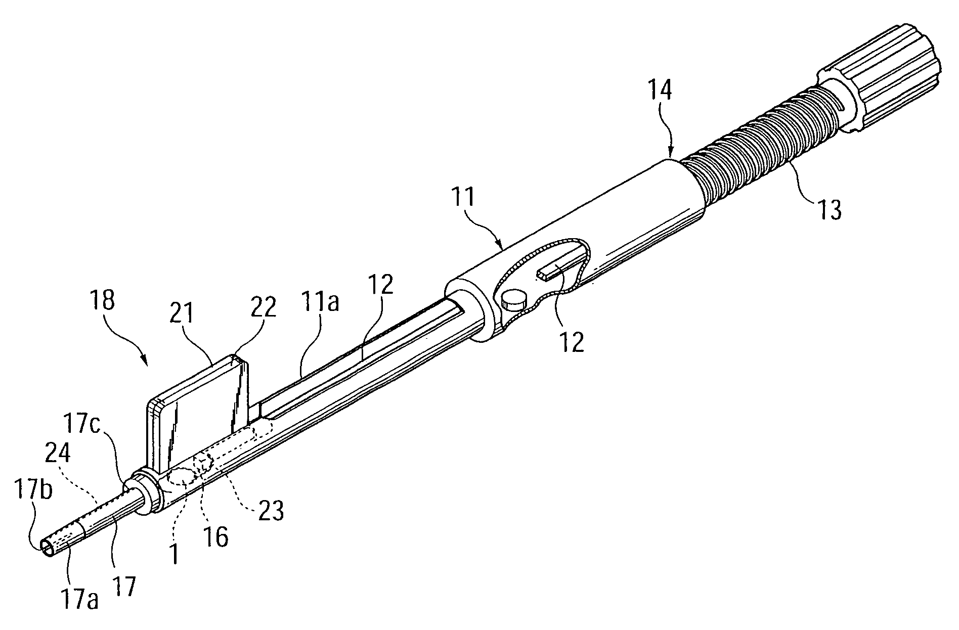
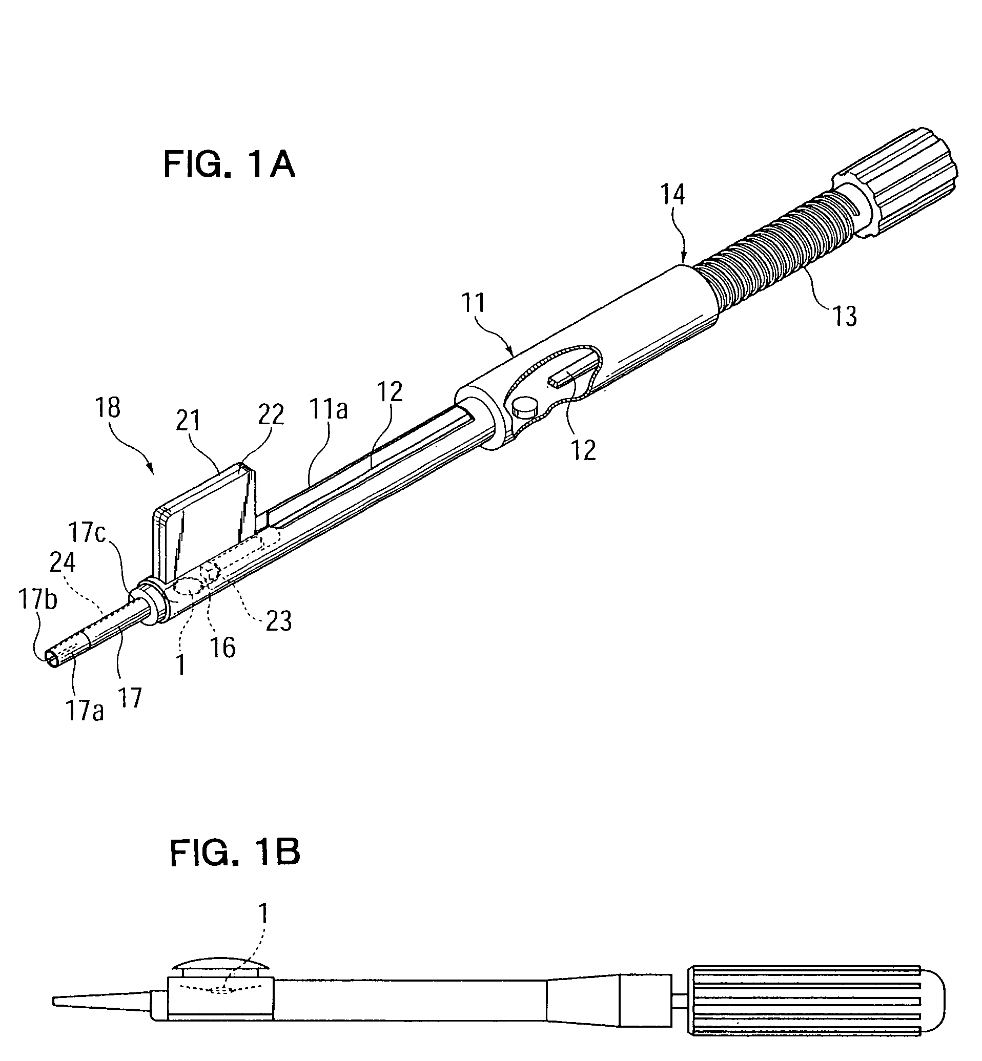
[0045]An intraocular-lens insertion device according to a first embodiment of the present invention will be described with reference to FIG. 1A.

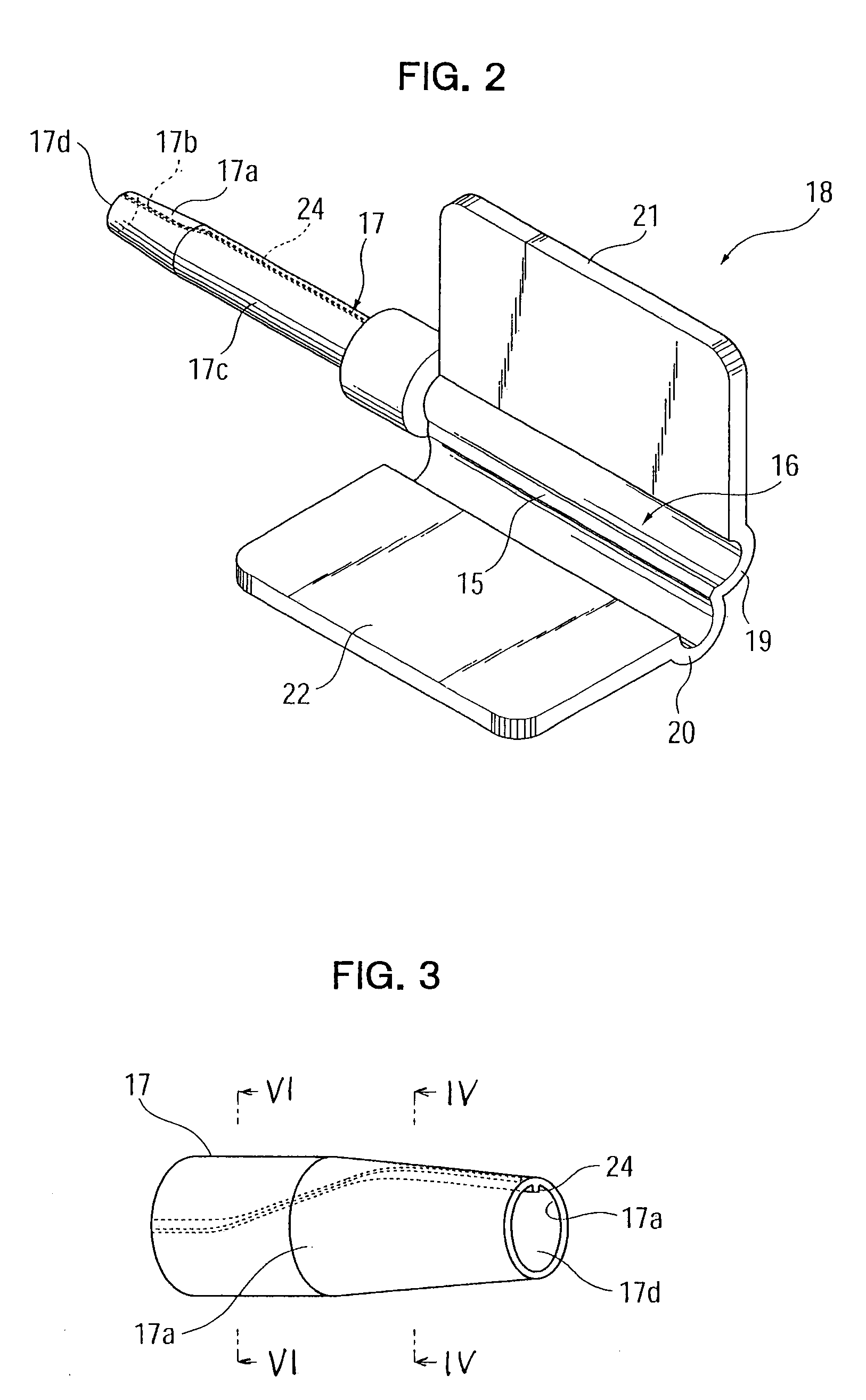
[0046]As shown in FIG. 1A, the intraocular-lens insertion device of the present embodiment includes a generally cylindrical, tubular device body 11; a push rod 12 fitted into the device body 11; a push-out mechanism 14 including a male-thread shaft 13 in screw-engagement with a female thread (not shown) formed on the inner wall surface of the device body 11; and an enclosing member 18, which has a lens receiving section 16 having a hinge portion 15, and an insertion tube 17 projecting forward from the lens receiving section 16.

[0047]An attachment groove 11a is formed in an upper portion of a tip end portion of the device body 11. The enclosing member 18 is loaded into the device body 11 via the groove 11a. The push rod 12 is rotatably connected, at its one end, to the male-thread shaft 13 and is supported by the device body 11 in such a mann...

second embodiment

[0062]FIG. 7 shows the guide portion 24 of an intraocular-lens insertion device according to a second embodiment of the present invention.

[0063]As shown in FIG. 7, the guide portion 24 is a groove 24c that is formed on the inner wall surface of the insertion tube 17. The groove 24c faces the axis of the insertion tube 17; i.e., the insertion tube axis, and axially extends. As in the case of the first embodiment, in the transitional region between the base end portion 17c and the insertion end portion 17a, the groove 24c changes its position rotationally about the axis of the insertion tube 17 by a predetermined angle. The intraocular lens 1 moves along the groove 24c while being guided by the groove 24c by virtue of its restoration force, and thus can be moved rotationally about the insertion tube axis. The intraocular-lens insertion device of the second embodiment is effectively used, particularly with a thick intraocular lens.

third embodiment

[0064]FIG. 8 shows the guide portion 24 of an intraocular-lens insertion device according to a third embodiment of the present invention.

[0065]As shown in FIG. 8, the guide portion 24 is a groove 24d that is formed in the insertion tube 17 in such a manner as to extend from the inner wall surface to the outer wall surface thereof, and axially extends. As in the case of the first embodiment, in the transitional region between the base end portion 17c and the insertion end portion 17a, the groove 24d changes its position rotationally about the axis of the insertion tube 17 by a predetermined angle. The intraocular lens 1 moves along the groove 24d while its peripheral edge is guided by the groove 24d, and thus can be moved rotationally about the insertion tube axis. The intraocular-lens insertion device of the third embodiment is effectively used, particularly with a thin intraocular lens.


PUM


Abstract

In an intraocular-lens insertion device for deforming a deformable intraocular lens to a smaller size and inserting the intraocular lens into an eye via an insertion tube, the insertion tube has such an inner wall shape as to cause the deformable intraocular lens to move rotationally about an insertion tube axis by a predetermined angle in the course of axial movement.

Description

BACKGROUND OF THE INVENTION[0001]1. Field of the Invention[0002]The present invention relates to an insertion device for a deformable intraocular lens that is inserted into the eye in place of the natural lens when the latter is physically extracted because of cataract, for a deformable sight corrective lens that is inserted into the eye only for the purpose of sight correction, or for a like deformable intraocular lens.[0003]2. Description of the Related Art[0004]In 1949, Ridley became the first to implant an artificial lens; i.e., an intraocular lens, into the human eye in place of the natural lens, which had become cloudy. Since then, implantation of an intraocular lens has been widely practiced as treatment for cataract.[0005]Japanese Patent Application Laid-Open (kokai) No. 58-146346 discloses deformable intraocular lenses that can be inserted into the eye through a small incision formed therein, such as a deformable intraocular lens that uses a deformable, elastic material hav...

Claims


Application Information

Patent Timeline
Patent Type & Authority Patents(United States)
IPC IPC(8): A61F9/00A61F9/007A61F2/16
CPCA61F2/1678
Inventor OHNO, KENICHIROSHINZAKI, KENICHIMASUDA, TAKASHI
Owner STAAR JAPAN
Why Eureka
Try Eureka