Direction finding system and method

a direction finding and direction technology, applied in direction finders using radio waves, multi-channel direction finding systems using radio waves, instruments, etc., can solve the problems of signal detection, signal demodulation performance, signal detection, direction of arrival estimation, etc., to reduce multiplex interference, increase the number of spread spectrum signals, and reduce the effect of multiplex interferen

Inactive Publication Date: 2009-01-13
L 3 COMM TITAN CORP
View PDF8 Cites 37 Cited by
  • Summary
  • Abstract
  • Description
  • Claims
  • Application Information

AI Technical Summary

Benefits of technology

[0004]By combining coded signals from different sets of less than all of the plurality of arrayed antennas, the present invention addresses a problem attendant to the direction finding system described in U.S. Pat. No. 6,384,784 B1, wherein multiplex interference between the spread spectrum signals increases with an increase in the number of spread spectrum signals that are summed and provided to the single receiver for demodulation. Such multiplex interference degrades direction of arrival estimation, signal detection, and signal demodulation performance. Accordingly, such multiplex interference restricts the number of antennas and the total space of potential antenna geometries that can be utilized in the direction finding system described in U.S. Pat. No. 6,384,784 B1 to detect and process signals in an unknown received signal environment.
[0005]By judiciously selecting the different sets of antennas prior to coding and combination, the present invention enables selection of antenna sets of limited size to reduce multiplex interference while enabling different sets of antennas to be selected to provide a flexible variety of geometries for detecting a large variety of signals in an unknown received signal environment.
[0006]The present invention utilizes this antenna set selection flexibility to accomplish, among other things, the goals of: (1) signal detection, (2) simultaneous signal demodulation and estimation of directions of arrival, and (3) characterization and de-cluttering of complicated signal environments.

Problems solved by technology

Such multiplex interference degrades direction of arrival estimation, signal detection, and signal demodulation performance.

Method used


Image

  • Direction finding system and method
  • Direction finding system and method
  • Direction finding system and method

Examples


Embodiment Construction

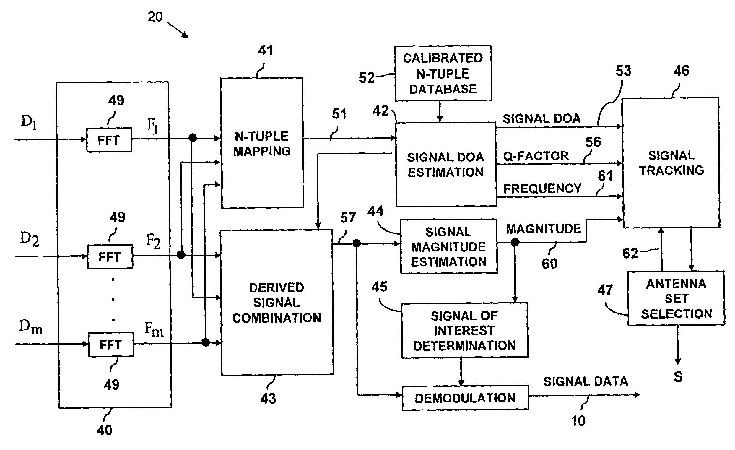
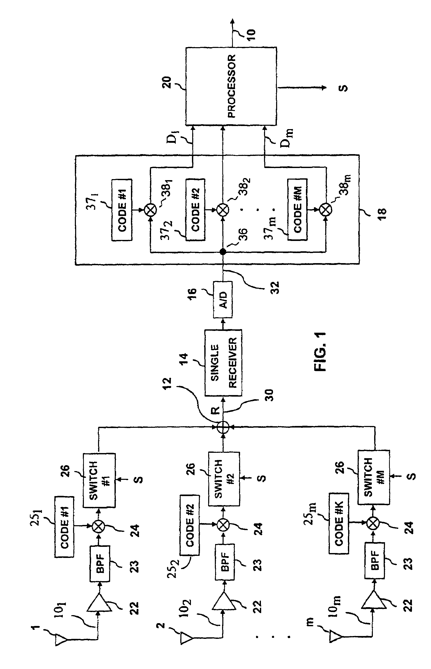
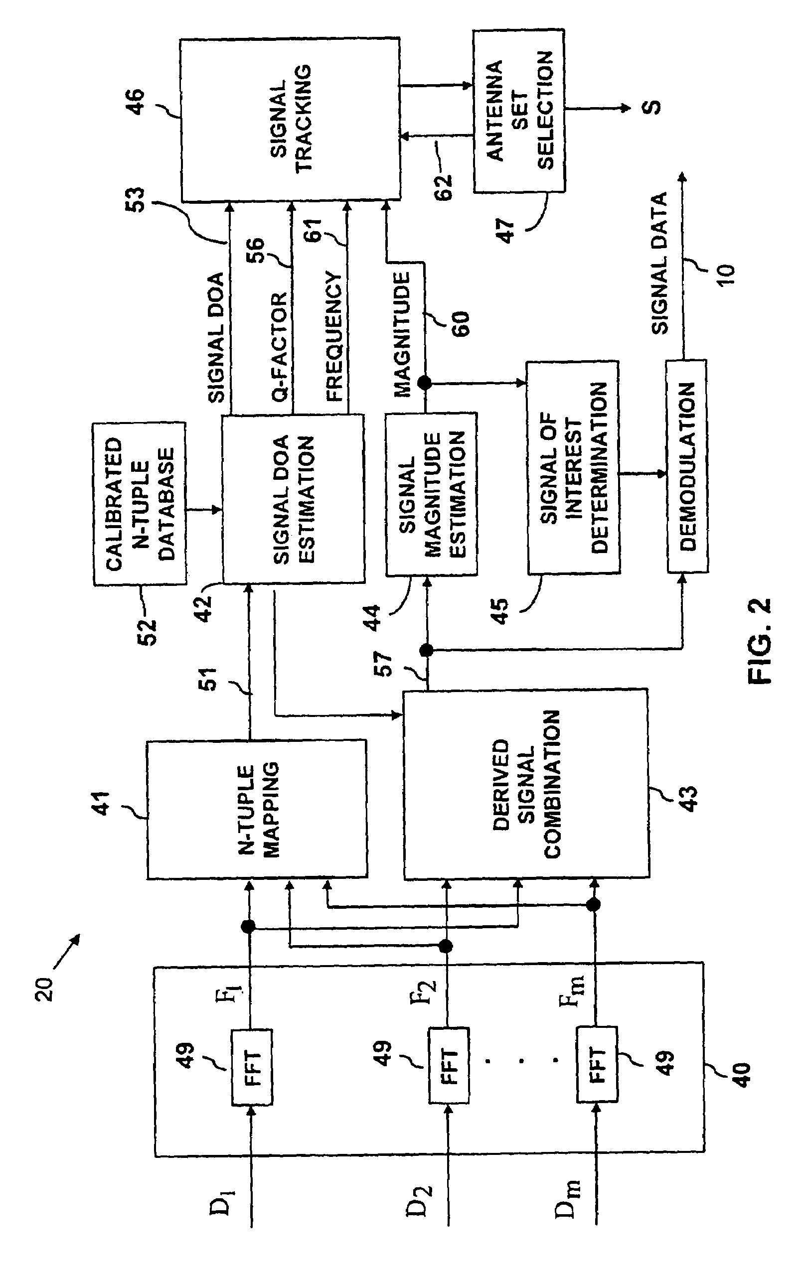
[0019]Referring to FIG. 1, one embodiment of a direction finding system according to the present invention for determining the direction of arrival of signals at a particular location includes an array of antennas 1, 2, . . . , m; a plurality of receive channels 101, 102, . . . , 10m respectively coupled to the antennas 1, 2, . . . , m; a signal combiner 12, a receiver 14, an analog-to-digital converter (A / D) 16, a signal derivation unit 18 and a signal processor 20. The plurality of antennas 1, 2, . . . , m are arrayed in a known pattern in relation to the particular location. Each of the receive channels 101, 102, . . . , 10m includes a low noise amplifier (LNA) 22, a band-pass filter (BPF) 23, a mixer 24, a code source 251, 252, . . . , 25m and a switch 26.

[0020]The number of antennas 1, 2, . . . , m in the antenna array and the particular configuration of the array are not constrained. The antenna aperture distance may be larger than one-half the wavelength of a particular signa...


PUM


Abstract

In a direction finding system, pluralities of signals provided by different sets of less than all of a plurality of arrayed antennas are code division multiplexed, downconverted by a single receiver, A / D converted and separated to derive signals that are processed to estimate the directions of arrival of the signals received by the different sets of antennas at different frequencies. The signals from different antennas are coded with different codes that have a common M-sequence and different phases for the different antennas. The derived signals are processed to detect the presence of signals and simultaneously demodulate and estimate the directions of arrival of signals by the antennas at the different frequencies. The different sets of antennas from which the received signals are provided for coding and multiplexing are selectively varied in accordance with the estimated directions of arrival and estimated magnitudes.

Description

BACKGROUND OF THE INVENTION[0001]The present invention generally pertains to electronic direction finding systems and methods and is specifically directed to determining the direction of arrival of a received signal.[0002]A prior art direction finding system for determining the direction of arrival at a particular location of signals received by a plurality of antennas that are arrayed in a known pattern in relation to the particular location is described in U.S. Pat. No. 6,384,784 B1. This prior art system includes an array of antennas in a predetermined configuration for receiving a signal from a modulated, or interfering, signal source. The individual outputs from each antenna are input to respective direct sequence spread spectrum modulators where each is multiplied by a unique pseudo-random number code, unique either in value or in time relationship. The spread spectrum outputs are summed and the summed output is demodulated and digitized to produce a digitized intermediate fre...

Claims


Application Information

Patent Timeline
Patent Type & Authority Patents(United States)
IPC IPC(8): G01S5/02G01S19/48
CPCG01S3/30G01S3/74G01S3/72
Inventor HAFF, ANDREWCIANOS, NICHOLASMARKS, SCOTT ENSIGN
Owner L 3 COMM TITAN CORP
Why Eureka
Try Eureka