Methods and apparatus for managing a flow of packets using change and reply signals

Inactive Publication Date: 2009-01-13
CISCO TECH INC
View PDF32 Cites 14 Cited by
  • Summary
  • Abstract
  • Description
  • Claims
  • Application Information

AI Technical Summary

Benefits of technology

[0009]In conventional network arrangements, a sending host reduces a transmission rate of a packet flow destined for a receiving host in response to a timeout condition caused by the sending host's failure to receive, from the receiving host, a particular number of acknowledgement messages for the packet flow. Such an operation is intended to reduce packet congestion along the path leading from the sending host to the receiving host thus enabling the sending host to improve delivery of the packet flow to the receiving host. For example, a sending host may provide a stream of video QoS class packets to the receiving host for viewing by an end-user at the receiving host. If significant network congestion occurs in a network area carrying the video packet stream, the receiving host will fail to acknowledge receipt of the video packets within a particular amount of time. When the sending host fails to receive a particular number of acknowledgements from the receiving host within that time (i.e., a timeout period), the sending host considers a timeout condition to have occurred. At that time, the sending host reduces the transmission rate of the video stream (the packet flow) in order to provide an opportunity for the congestion to clear along the path leading to the receiving host.
[0012]In contrast to conventional mechanisms that attempt to improve delivery of a flow of packets to a receiving host by lowering the transmission rate of the packet flow in response to timeout conditions caused by the lack of acknowledgement messages from the receiving host, the invention is directed to techniques for controlling a flow of packets using signals between data communications devices in the network and the sending host. The signals permit the sending host and / or the data communications devices to adjust their operations to changing network conditions earlier than conventional mechanisms that rely on timeout conditions triggered by the absence of acknowledgement messages from the receiving host.
[0020]It should be understood that the change signal from the data communications device to the source, and the reply signal from the source to the data communications device enable the source and data communications device to quickly adjust their operations to changing network conditions before the conditions significantly hinder rendering of the service at the receiving host. Accordingly, the invention provides an improvement in response time over conventional mechanisms that wait until a timeout condition occurs.

Problems solved by technology

If significant network congestion occurs in a network area carrying the video packet stream, the receiving host will fail to acknowledge receipt of the video packets within a particular amount of time.
Unfortunately, by the time the sending host reacts (e.g., changes the transmission rate), an end-user at the receiving host may have endured significant problems caused by packet delays and perhaps packet drops (e.g., video image hesitation and lost video image segments).
Such annoyances may result in the loss of goodwill or even loss of repeat business from the end-users (e.g., subscribers).
Furthermore, there is no guarantee that the packet delays and drops of the video stream were due to congestion caused by the sending host.
Rather, the congestion may have been caused by a different source such as by extended bursts of low priority packets (e.g., general data packets) from other sending hosts.
Accordingly, transmitting the remaining video stream at a slower rate may only serve to further annoy the end-user at the receiving host since video packets of the video service may arrive at an even slower rate due to the lowered transmission rate.

Method used


Image

  • Methods and apparatus for managing a flow of packets using change and reply signals
  • Methods and apparatus for managing a flow of packets using change and reply signals
  • Methods and apparatus for managing a flow of packets using change and reply signals

Examples


example

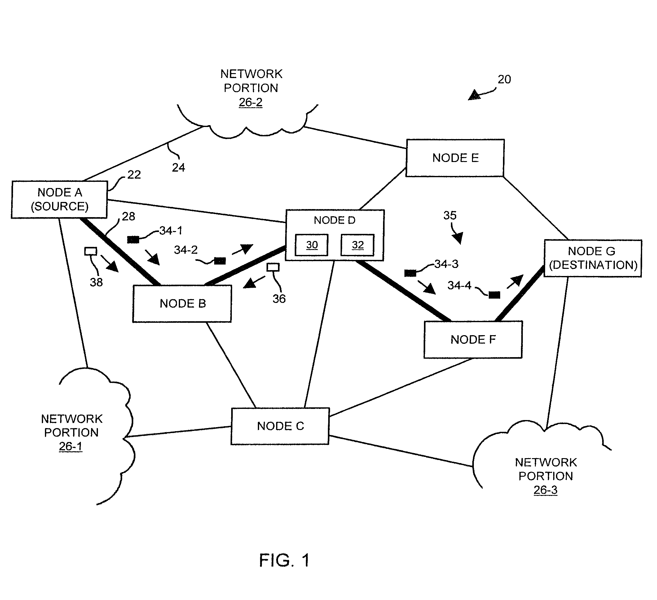
[0074]The operation of the source 50 (NODE A) and the data communications device 40 (NODE D) will now be further explained using the following example. Suppose that NODE A is a sending host that provides, as a service, a stream of video images (a video service) to an end-user at NODE G, a receiving host (see FIG. 1). The end-user watches the video service as it arrives and is rendered on-the-fly.

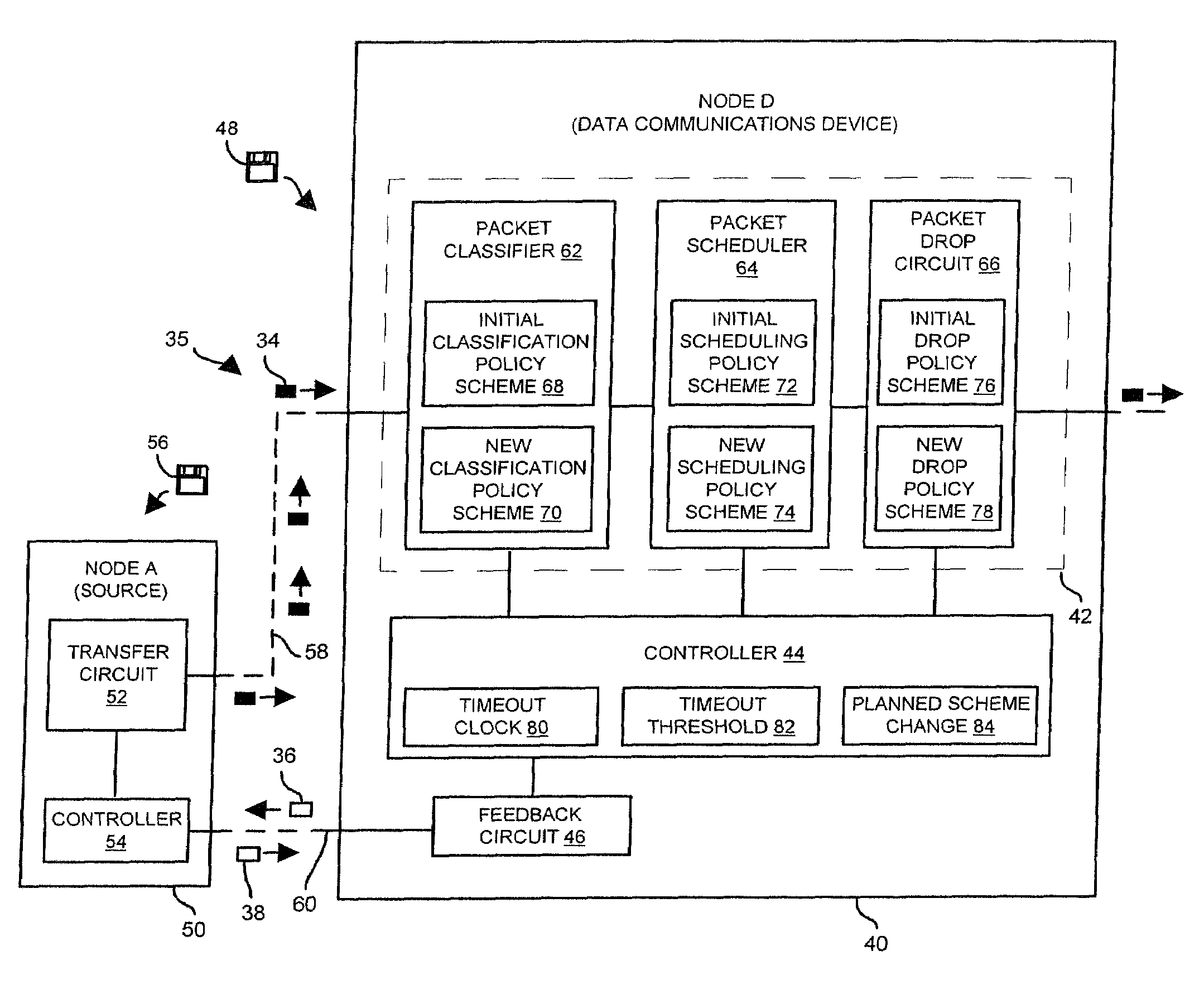
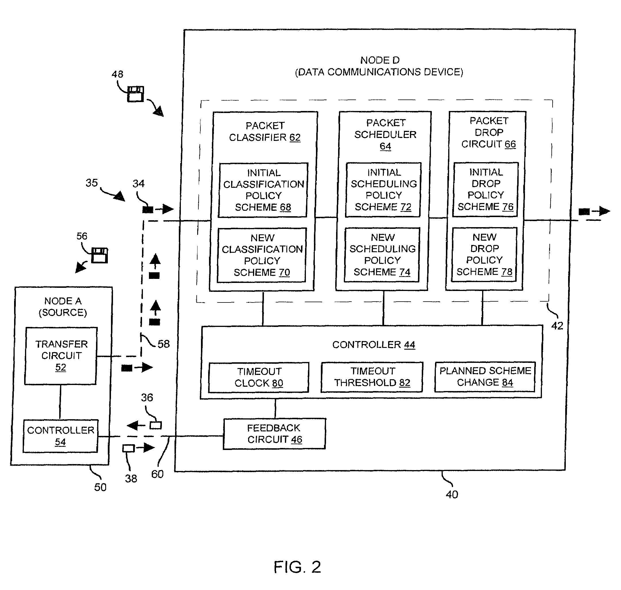
[0075]Further suppose that the data communications device 40 initially routes packets using a FIFO classification policy (see the initial classification policy scheme 68 in FIG. 2), a Weighted Fair Queuing scheduling policy (see the initial scheduling policy scheme 72), and a Random Early Detection drop policy (see the initial drop policy scheme 76). Such policies initially may be the most suitable policies for network conditions existing around NODE D.

[0076]Suppose that the network conditions around NODE D change shortly after NODE A begins providing the video service (i.e., the packet flow...


PUM


Abstract

Techniques are provided for controlling a flow of packets in a data communications device. A first technique involves transferring packets of a particular packet flow based on an initial policy scheme, and planning a scheme change to change the initial policy scheme to a new policy scheme based on conditions within the data communications device existing while transferring the packets of the particular flow based on the initial policy scheme. The first technique further involves providing a change signal to the source of a particular packet flow (e.g., a sending host). The change signal indicates that the data communications device has planned the scheme change. Additionally, the first technique involves processing the scheme change based on either a reply signal from the source or an absence of a reply signal from the source.Another technique involves outputting packets of a particular packet flow to a data communications device that transfers the packets of the particular packet flow based on an initial policy scheme. Additionally, the technique involves receiving, in response to the outputted packets of the particular packet flow, a change signal from the data communications device. The change signal indicates that the data communications device has planned a scheme change to change the initial policy scheme to a new policy scheme. Furthermore, the technique involves providing, to the data communications device, a reply signal that provides direction for processing the scheme change.

Description

[0001]This patent application is a continuation of U.S. patent application Ser. No. 09 / 340,524, filed Jun. 28, 1999, now U.S. Pat. No. 6,628,610, entitled “METHODS AND APPARATUS FOR MANAGING A FLOW OF PACKETS USING CHANGE AND REPLY SIGNALS”. The entire contents and teachings of this referenced application are hereby incorporated by reference herein. A typical data communications network includes multiple host computers (or hosts) that communicate with each other through a system of data communications devices (e.g., switches and routers) and transmission media (e.g., fiber-optic cable, electrical cable, and / or wireless connections). In general, a sending host exchanges data with a receiving host by packaging the data using a standard protocol or format to form one or more network packets or cells (hereinafter generally referred to as packets), and transferring the packaged data to the receiving host through a system of data communications devices and transmission media. The receivin...

Claims


Application Information

Patent Timeline
IPC IPC(8): H04L12/26G06F11/00H04L12/56
CPCH04L47/10H04L47/26H04L47/30
Inventor WACLAWSKY, JOHN G.CHAWLA, HAMESH
Owner CISCO TECH INC
Why Eureka
Try Eureka