Liquid diagnostic contact lens

Active Publication Date: 2009-01-20
LIN PO KANG
View PDF1 Cites 7 Cited by
  • Summary
  • Abstract
  • Description
  • Claims
  • Application Information

AI Technical Summary

Benefits of technology

[0011]The liquid diagnostic contact lens according to the present invention is kept on a fixed position of the eye without turning or replacing diagnostic contact l

Problems solved by technology

It is inconvenient to use and may e

Method used


Image

  • Liquid diagnostic contact lens
  • Liquid diagnostic contact lens
  • Liquid diagnostic contact lens

Examples


Example

[0018]The accompanying drawings are included to provide a further understanding of the invention, and are incorporated in and constitute a part of this specification. The drawings illustrate embodiments of the invention and, together with the description, serve to explain the principles of the invention.

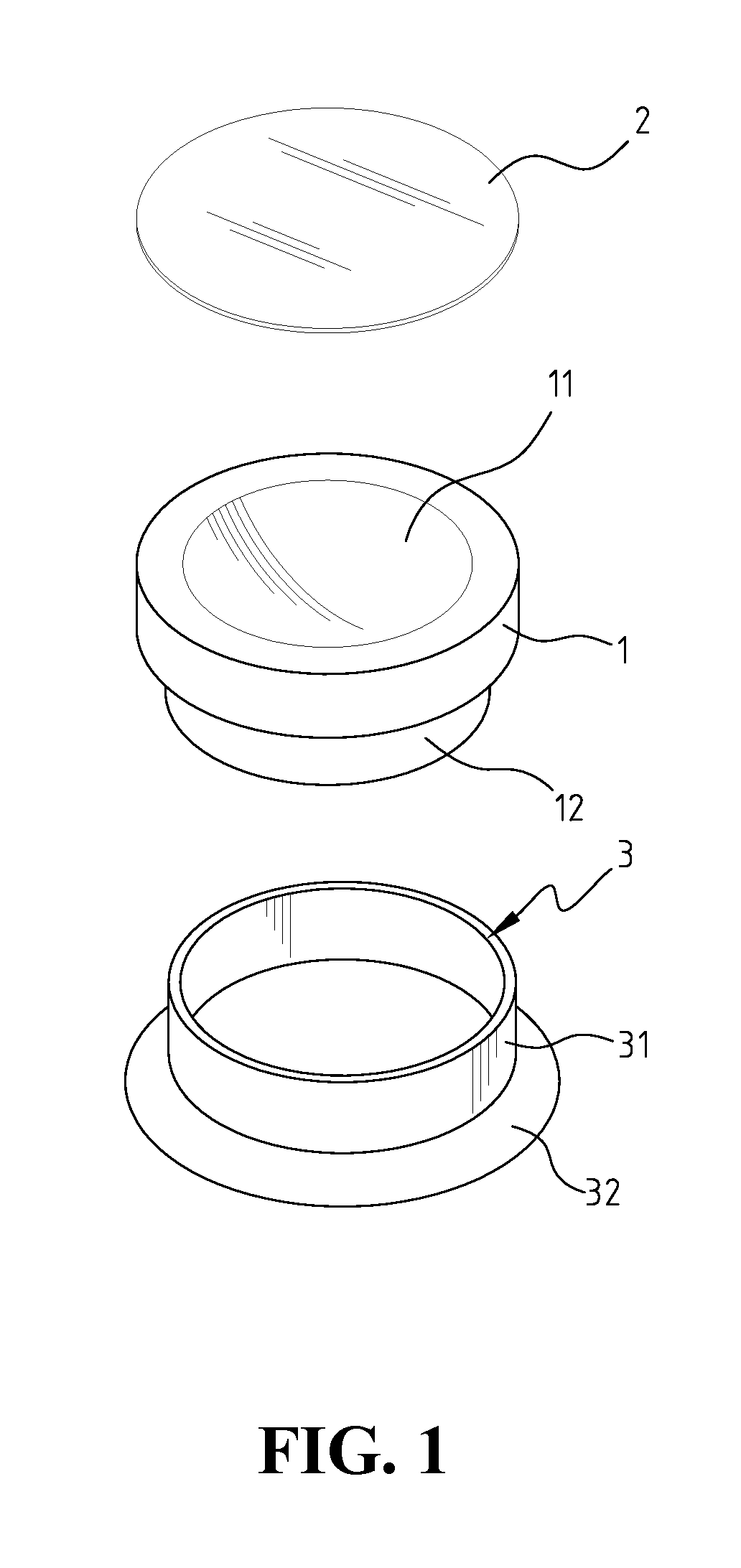
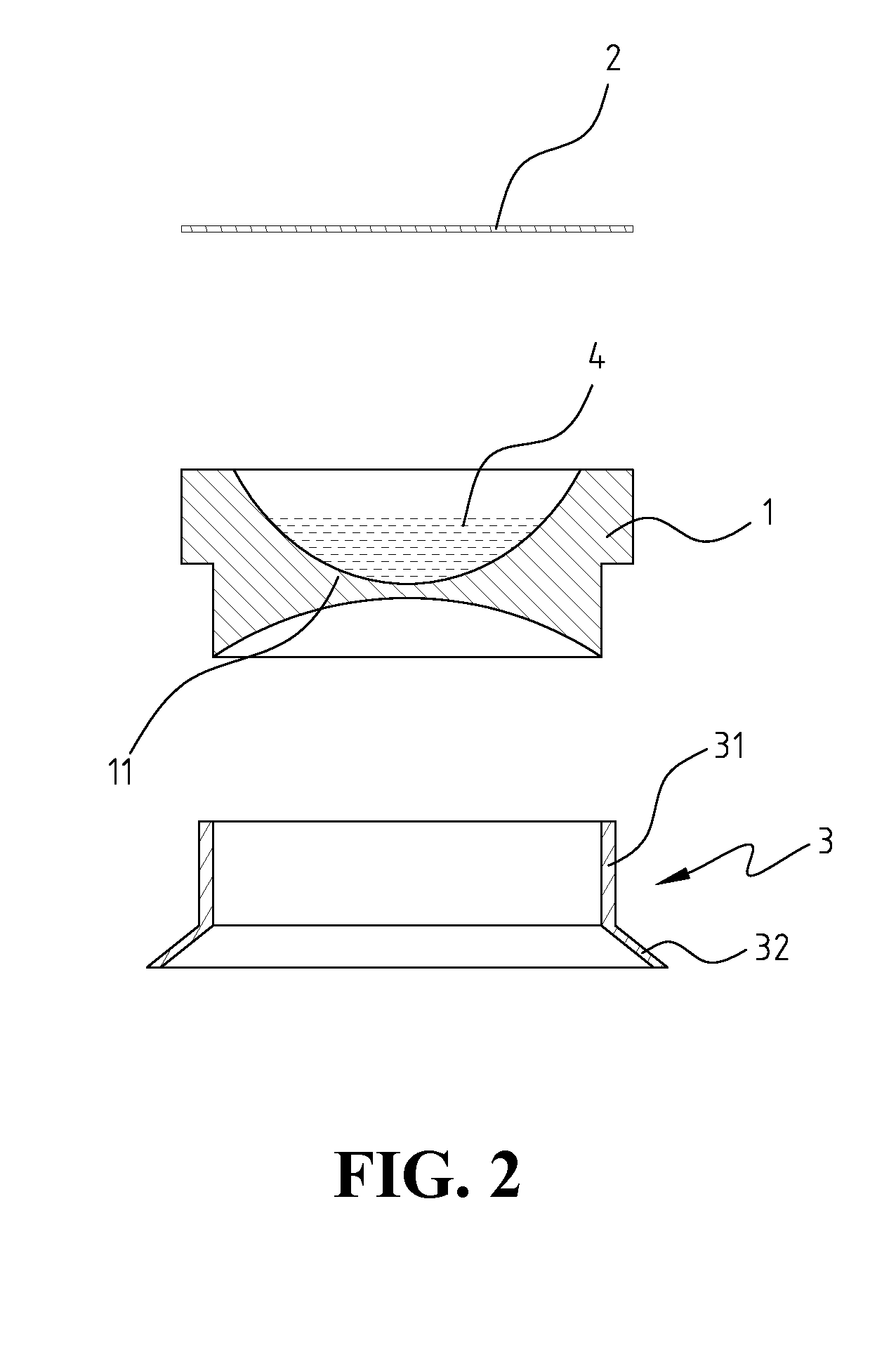
[0019]FIGS. 1 to 3 illustrate a liquid diagnostic contact lens adapted for ophthalmic inspections or operations according to a first embodiment of the present invention. The liquid diagnostic contact lens includes a main body 1, a transparent plate 2, a supporting element 3, and a suitable heavy fluid 4. The main body 1 includes a concave lens 11 configured integrally at a center thereof, and a lower portion 12 configured integrally at a bottom thereof. The lower portion 12 is adapted for engaging with the supporting element 3. The concave lens 11 has a top surface and a bottom surface. The top surface of the concave lens 11 is a concave surface having a certain curvature which is no...


PUM


Abstract

A liquid diagnostic contact lens includes a main body having a concave lens, and a supporting element disposed at a bottom of the main body. A heavy fluid is placed on a top surface of the concave lens. A transparent plate is sealed over the top surface of the concave lens so as to define an encapsulating room and encapsulate the heavy fluid therein. In operation, an ophthalmologist places the supporting element onto the eye, and examines various interior spots of the eye by adaptively adjusting the eye. The liquid diagnostic contact lens is tilted along with the eye and the top surface of the heavy fluid is kept horizontal so the heavy fluid is formed as prisms of different diopters. Thus, the liquid diagnostic contact lens can examine various spots of the interior of the eye.

Description

BACKGROUND OF THE INVENTION[0001]1. Field of the Invention[0002]The present invention relates generally to a magnification device for ophthalmic examination and surgery.[0003]2. The Prior Arts[0004]When conducting a diagnostic examination or a therapeutic procedure to an eye, an ophthalmologist often needs to use opthalmoscope, diagnostic contact lens, slit lamp, or ultrasound device, etc. to diagnose the eye condition and then treat thereby.[0005]A conventional diagnostic contact lens is a flat lens, a concave lens, or a prism. A flat lens is often used for examining a posterior pole of the eye. However, in viewing a peripheral retina, various prisms of different diopters are often required. The ophthalmologist directly places the prism onto the eye. The prism is turned or replaced with another one having a different diopter according to the position to be examined. It is inconvenient to use and may even accidentally cause eye injuries.SUMMARY OF THE INVENTION[0006]A primary object...

Claims


Application Information

Patent Timeline
IPC IPC(8): A61B3/00
CPCA61B3/125A61B5/6821
Inventor LIN, PO-KANG
Owner LIN PO KANG
Why Eureka
Try Eureka