Target tissue localization device

a tissue localization and target technology, applied in the field of target tissue localization devices, can solve the problems of misleading indications, difficult to feel devices, and relatively high clip prices, and achieve the effect of large cross-sectional area

Inactive Publication Date: 2009-01-20
ARTEMIS MEDICAL
View PDF68 Cites 58 Cited by
  • Summary
  • Abstract
  • Description
  • Claims
  • Application Information

AI Technical Summary

Benefits of technology

[0006]The present invention is directed to a target tissue localization device including an elongate placement device having first and second members being longitudinally movable relative to one another. An anchor is secured to the first and second members and is movable from a first, radially contracted configuration to a second, radially expanded configuration. The placement device and anchor are sized and configured for use in localization of target tissue. According to one aspect of the invention the anchor is a tubular mesh anchor. According to another aspect of the invention the anchor has a sufficiently large cross-sectional area when in the second, radially expanded configuration to substantially eliminate inadvertent dislodgment of the anchor once radially-expanded.
[0011]The invention may also include structure which may enhance ultrasound visibility. Invention may include certain treatment, grooves, slits, or other structure to enhance the ultrasonic visibility of the placement device or the delivery needle, or both. Also, the mesh anchor may provide sufficient reflectivity so that treatment of the placement device and delivery needle is not required. Other techniques for enhancing remote visualization, such as radiopaque markers, can also be used.
[0013]The present invention provides a simple, relatively inexpensive, very stable localization device to locate a lesion or other target tissue, typically within the breast of a patient, for subsequent biopsy, excision, intervention, or other purpose. The localization device is easy to insert, deploy, reposition if needed, and remains anchored at the target site substantially better than conventional localization needles. Further, the invention aids relocation of the target tissue by being configured to permit location by palpation by the surgeon in the operating suite. This permits the surgeon to proceed using much less radical techniques, which may be both cosmetically and surgically advantageous.

Problems solved by technology

Also, because the clip is necessarily attached to a single position at the periphery of the biopsy site, rather than the center of the biopsy site, its location may provide a misleading indication of the location of diseased tissue during any subsequent medical intervention.
The clip is also relatively expensive.
Additionally, these devices are not easily felt by external palpation and the tip is difficult to locate without dissection into the tissues; this prevents a surgical approach which may be more cosmetically advantageous and surgically appropriate than dissecting along the tract of the needle.
This procedure suffers from some of the same problems associated with the use of barbed or hooked wires.
This procedure also has certain problems, including the creation of discontinuities along the carbon trail.

Method used


Image

  • Target tissue localization device
  • Target tissue localization device
  • Target tissue localization device

Examples


Embodiment Construction

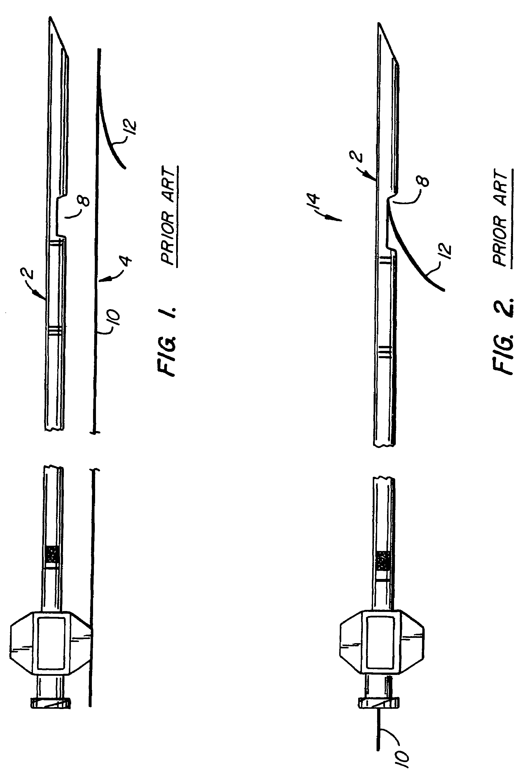
[0029]FIG. 1 illustrates a conventional hollow insertion needle 2 placed next to its associated hook wire 4. Insertion needle 2 has a sharpened tip 6 and an opening 8 set back away from tip 6. Hook wire 4 includes a shaft 10 and a barb 12 extending off the distal end of the shaft. Insertion needle 2 is relatively stiff or rigid while hook wire 4 is flexible but resilient. FIG. 2 illustrate the localization assembly 14 made up of the insertion needle 2 and hook wire 4 of FIG. 1 with the barb 12 extending from opening 8. The condition of localization assembly 14 in FIG. 2 is that which would be after tip 6 of insertion needle 2 has been properly placed relative to the target tissue and hook wire 4 has been pulled proximally causing barb 12 to extend from opening 8 and pass into the patient's tissue. As discussed above, this reliance on a thin barb 12 to ensure that assembly 14 does not move after placement is not particularly well-founded; breast tissue is generally quite soft and per...


PUM


Abstract

A target tissue localization device includes a tubular mesh anchor element that is secured to a placement device. In use, the localization device is passed through the patient's skin to the target tissue, creating a tissue track. The tubular mesh anchor element is located at the target tissue and expanded from a contracted to an expanded configuration. Methods for localizing a lymph node are also described. After determining the position of the lymph node, a localization device, which includes an anchor element, is localized near or within the lymph node. The anchor element is then expanded.

Description

[0001]This application is a continuation of U.S. application Ser. No. 10 / 134,802, filed on Apr. 29, 2002 now U.S. Pat. No. 6,758,855, which is a continuation of U.S. application Ser. No. 09 / 678,508, filed on Oct. 2, 2000, now U.S. Pat. No. 6,409,742, which is a continuation of U.S. patent application Ser. No. 09 / 376,678, filed on Aug. 18, 1999, now U.S. Pat. No. 6,179,860, which patent claims the benefit of the following Provisional Patent Applications: Biopsy Localization Device, Application No. 60 / 097,126, filed Aug. 19, 1998 and Biopsy and Tissue Localization Device, Application No. 60 / 106,733, filed Nov. 2, 1998, by FULTON, Richard E. All of the above-mentioned patents and applications are herein expressly incorporated by reference in their entirety.BACKGROUND[0002]In the U.S. alone approximately one million women will have breast biopsies because of irregular mammograms and palpable abnormalities. Biopsies can be done in a number of different ways for non-palpable lesions, incl...

Claims


Application Information

Patent Timeline
Patent Type & Authority Patents(United States)
IPC IPC(8): A61M29/00A61B10/02A61B17/34A61B19/00A61M25/04
CPCA61B19/54A61M25/04A61B2019/5408A61B90/39A61B2090/3908
Inventor FULTON, III, RICHARD EUSTISDUBRUL, WILLIAM R.
Owner ARTEMIS MEDICAL
Why Eureka
Try Eureka