Interbody fusion grafts and instrumentation

a fusion graft and instrumentation technology, applied in the field of implants, can solve the problems of spinal disc displacement or damage, pain and instability, nerve damage, muscle weakness, etc., and achieve the effects of maintaining distraction, reducing the area of tissue impacted, and maintaining disc heigh

Inactive Publication Date: 2009-01-20
WARSAW ORTHOPEDIC INC
View PDF61 Cites 621 Cited by
  • Summary
  • Abstract
  • Description
  • Claims
  • Application Information

AI Technical Summary

Benefits of technology

[0012]Other instruments included for use in the present invention include scrapers, rotating scrapers, and impacting or “slap” hammers for driving the implants into position. The slap hammer allows for controlled impacting force and removal of the chisel after cutting.
[0013]Another aspect of the present invention includes a nerve retractor blade assembly for manipulation of neural structures such as the dural sac and traversing nerve root with minimal trauma to the respective structures. The assembly includes a retractor having a channel adapted to receive a retractor blade, a retractor blade and can include at least one pin, preferably two pins, for securely fixing the positioning of the retractor assembly and blade proximal to the intervertebral space. The blade can be adapted for engagement with the retractor and for extending into the intervertebral space to provide anchorage proximal to the disc space, maintain disc height and maintain distraction. The nerve retractor also includes a handle attached at an angle to the channel. In a preferred embodiment, the retractor channel is provided in the form of a concave channel. It is also contemplated that the retractor channel can be formed in a variety of other shapes, for instance, rectangular and broadened V-shaped channels are also included within the present invention.
[0014]Yet another aspect of the present invention includes a protective guide sleeve. The protective sleeve includes a body having a hollow core for receiving instruments for performing surgery. In addition, the protective sleeve provides a narrow but unobstructed passageway to the intervertebral space and minimizes the area of tissue impacted by the surgery. Preferably the protective sleeve includes a first and a second distractor fin that can be inserted into the intervertebral space to maintain the space height and alignment of the vertebrae. The protective sleeve provides protection for neural structures and prevents encroachment of the neural structures into the surgical area. The protective sleeve allows use of depth stop on surgical tools. Preferably, the protective sleeve includes at least one window to facilitate visualization. The instruments for preparing and inserting spinal fusion implants can be received within the protective sleeve. Such instruments include the implant holder engaged to an implant, the bone chisel, scrapers, and drills provided in the present invention.
[0016]It is another object of the present invention to provide an implant holder to releasably secure the implant and facilitate impaction of the implant into position within the intervertebral space.

Problems solved by technology

Pain and instability are caused by compression of the spinal nerve roots because the damaged discs protrude into the vertebral canal and do not provide sufficient biomechanical support for the full range of vertebral motion.
The spinal discs may be displaced or damaged due to trauma, disease or aging.
A herniated or ruptured annulus fibrosis may result in nerve damage, pain, numbness, muscle weakness, and even paralysis.
Furthermore, as a result of the normal aging processes, discs dehydrate and harden, thereby reducing the disc space height and producing instability of the spine and decreased mobility.
However, patients who have failed to respond to conservative treatment and who have demonstrable disc pathology often require surgical correction.
Current treatment methods have been unable to accurately control the endplate removal using conventionally designed chisels, scrappers and cutters.
Use of conventional surgical instruments does not adequately control the depth of cut into the disc space nor provide a means to accurately the countersink the implant into the prepared cavity-particularly for non threaded impacted.
Furthermore, current methodologies do not provide sufficient protection of the neural structures during surgery to prevent neural injury.
While it is desirable to use natural bone grafts as implants, use of bone is often limited because of a small supply of suitable sources.
Xenografts from non-humans, animals, suffer from rejection problems once implanted.
Removal of an autograft requires further surgery and is limited in amount and structural integrity by the patient's anatomy.
Much of the donor bone is wasted, particularly the remnants of the slices from the diaphysis used to provide the dowels as well as the end portions of the long bone which cannot be utilized.
Thus, these portions of the femur are not considered suitable for forming cortical dowels having the required dimensions for inserting into vertebral spaces.

Method used


Image

  • Interbody fusion grafts and instrumentation
  • Interbody fusion grafts and instrumentation
  • Interbody fusion grafts and instrumentation

Examples


Embodiment Construction

[0108]For the purposes of promoting an understanding of the principles of the present invention, reference will now be made to the embodiments illustrated in the drawings, and specific language will be used to describe the same. It will nevertheless be understood that no limitation of the scope of the invention is intended thereby. Any alterations and further modification in the described processes, systems, or devices, and any further applications of the principles of the invention as described herein are contemplated as would normally occur to one skilled in the art to which the invention relates.

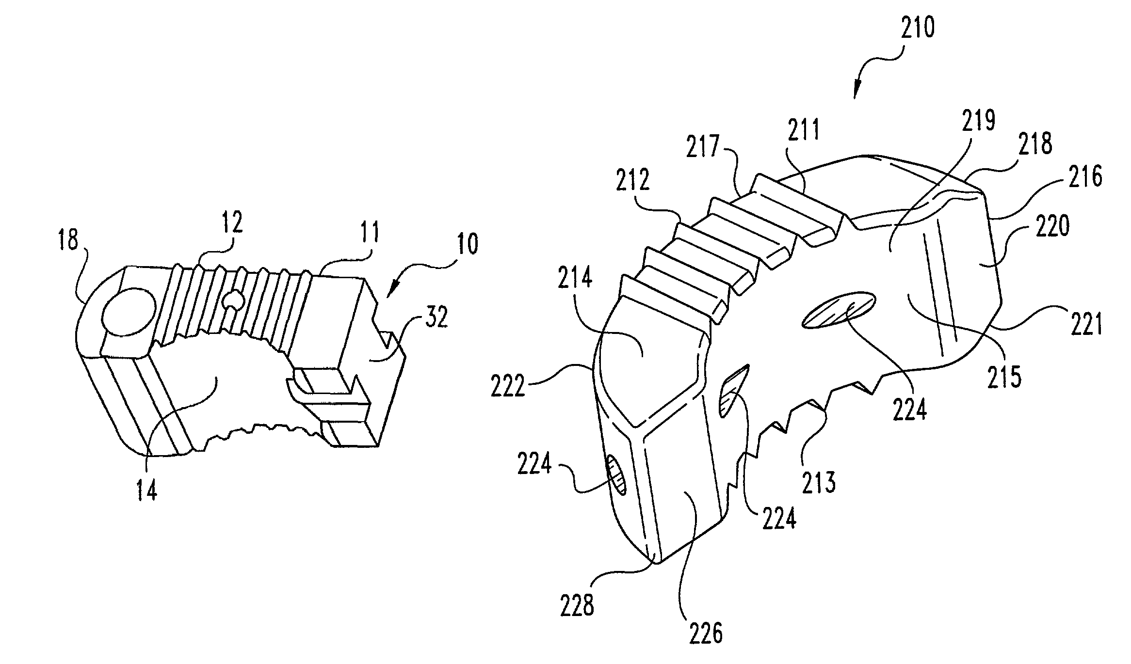
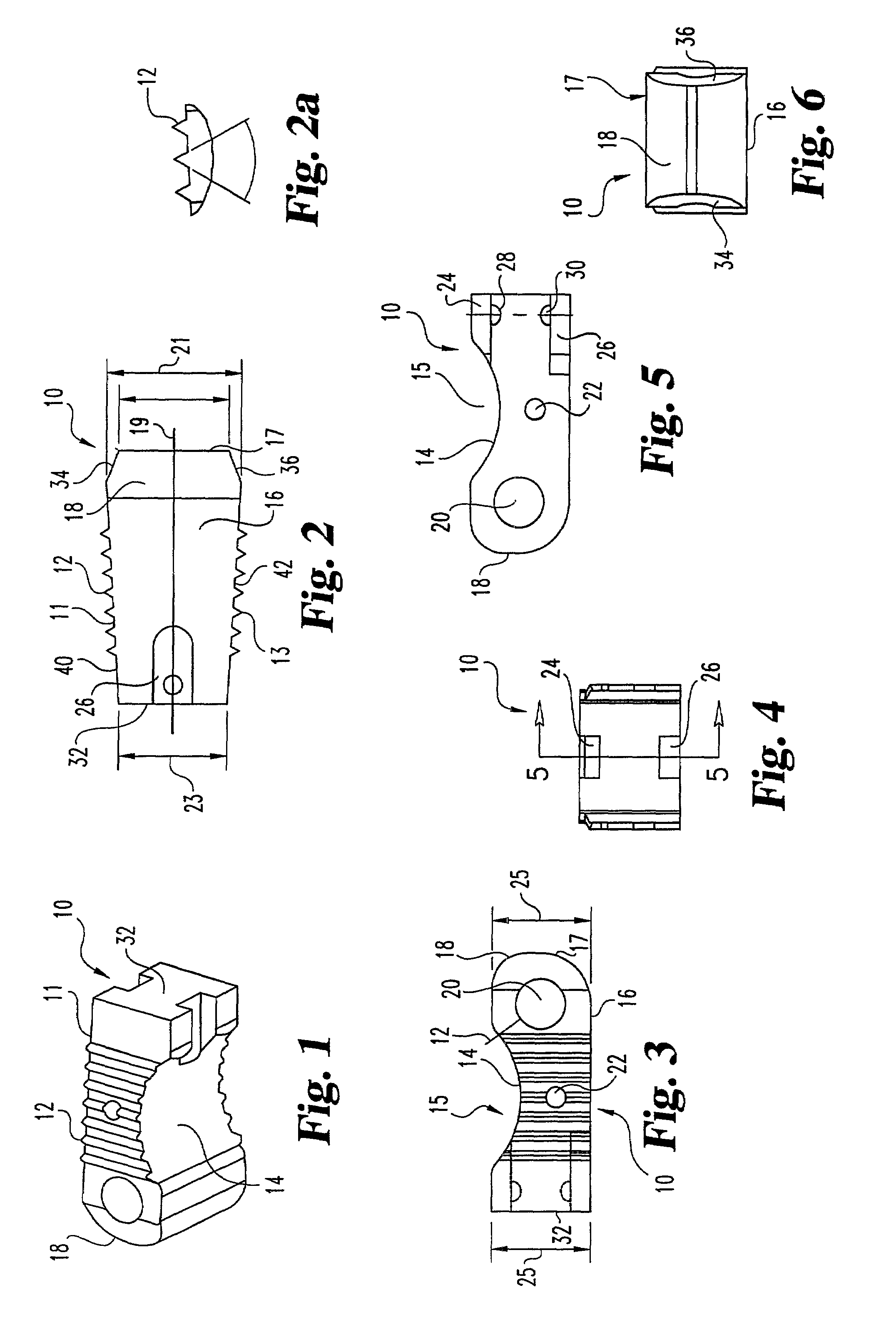
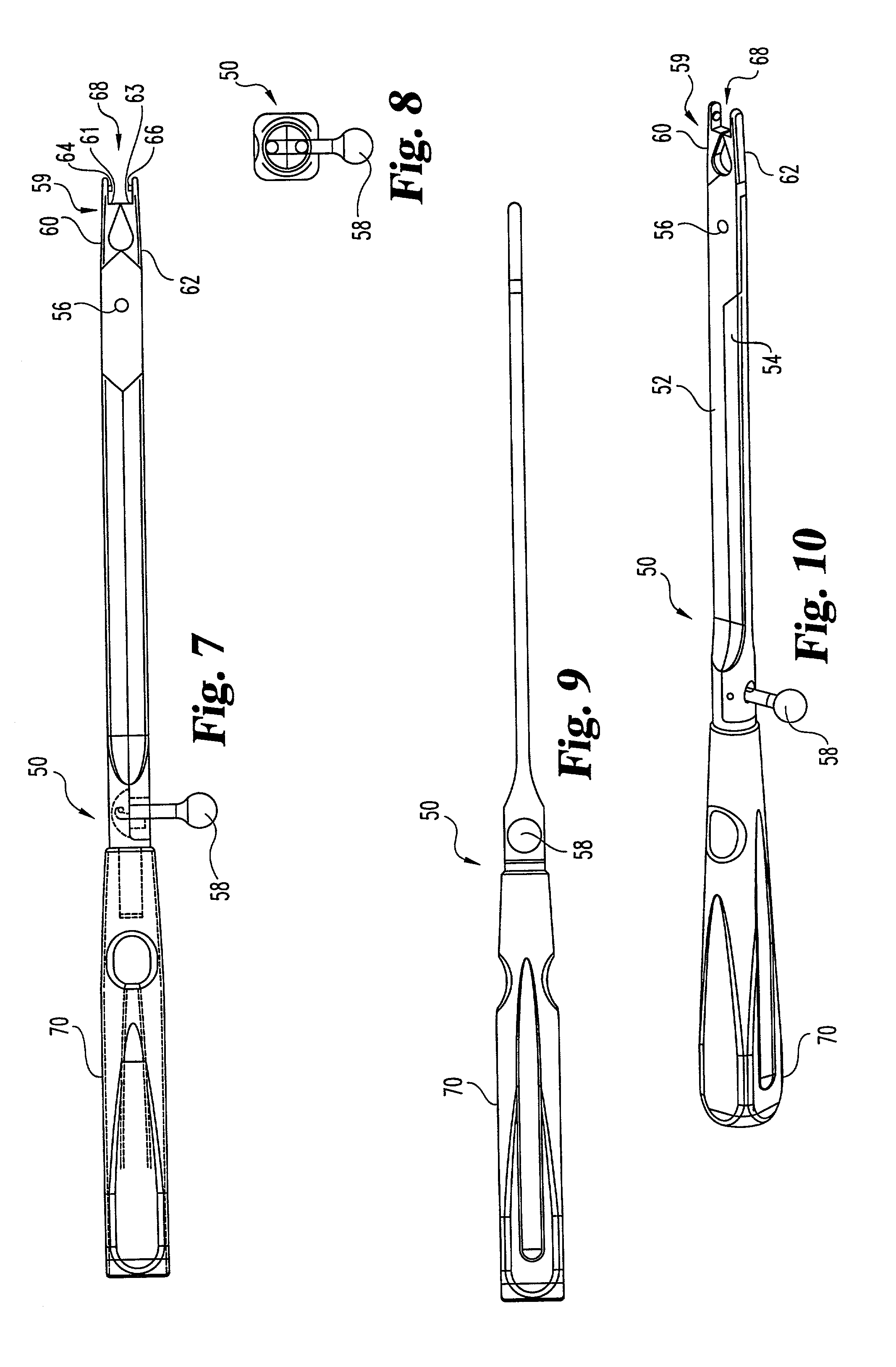
[0109]This invention provides bone implants for insertion into the intervertebral spaces between adjacent vertebrae following discectomy. The bone implants are useful for maintaining and / or restoring a desired spacing between adjacent vertebrae. The bone implants of the present invention include a recessed area that serves as a depot for receiving osteogenic material, thereby enhancing bo...


PUM


Abstract

This invention relates to implants formed from donor bone for use in lumbar interbody fusion procedures and instruments for performing such procedures. The implants are formed to include a concave surface formed from a portion of the medullary canal of a long bone. The concaved surface defines a recess in the implant that serves as a depot for osteogenic material. Specific instruments for inserting the implants prepared according to this invention and for preparing the intervertebral space to receive the implants are also provided.

Description

CROSS-REFERENCE TO RELATED APPLICATION[0001]The present application claims priority to and is a divisional of U.S. patent application Ser. No. 09 / 698,623 filed on Oct. 27, 2000, now U.S. Pat. No. 6,610,065, which is a divisional of U.S. patent application Ser. No. 09 / 181,353 filed on Oct. 28, 1998, now U.S. Pat. No. 6,174,311; and is a Continuation-in-Part of pending U.S. patent application Ser. No. 09 / 701,933, filed on Aug. 20, 2001, which is the national stage of International Application No. PCT / US98 / 17769, filed on Aug. 27, 1998, published as WO 99 / 09914.FIELD OF THE INVENTION[0002]The present invention relates to implants for use in lumbar interbody fusion procedures and instruments for performing such procedure. More specifically, this invention relates to implants formed from donor bone that are useful to restore disc height and promote bone fusion after discectomy and to instruments and methods for preparing the intervertebral space and inserting the implant into an interver...

Claims


Application Information

Patent Timeline
Patent Type & Authority Patents(United States)
IPC IPC(8): A61F2/44A61B17/70A61B17/02A61B17/56A61B17/16A61B17/17A61B17/58A61B17/88A61B17/92A61B19/00A61F2/00A61F2/28A61F2/30A61F2/46
CPCA61B17/1671A61B17/1757A61F2/4455A61F2/4601A61F2/4611A61B17/1604A61B17/1659A61B17/88A61B19/54A61B2017/0256A61B2017/922A61F2/3094A61F2/442A61F2002/2817A61F2002/2835A61F2002/2839A61F2002/30131A61F2002/30158A61F2002/30168A61F2002/30192A61F2002/3028A61F2002/30774A61F2002/3082A61F2002/30848A61F2002/30879A61F2002/30892A61F2002/448A61F2002/4624A61F2002/4627A61F2002/4628A61F2002/4649A61F2002/4681A61F2230/0013A61F2230/0026A61F2230/0041A61F2230/0043A61F2230/0063A61B17/1739A61B2017/1778Y10S606/909Y10S606/914A61B90/39A61B17/1778A61F2002/30845A61F2/4603
Inventor BRANCH, CHARLES L.LIU, MINGYANBOYD, LAWRENCE M.JOSSE, LOIC
Owner WARSAW ORTHOPEDIC INC
Why Eureka
Try Eureka