
Modular up-draft pressure pulse bag house

a module and bag house technology, applied in the field of module up-draft pressure pulse bag house, can solve the problems of inadvertent recycling of cleaned air, inability to clean air pass through the filter bag in the wrong direction, and limited size of the portable bag house, etc., to achieve high volume requirements, simplify the bag cleaning operation, and high pressure

Inactive Publication Date: 2009-01-20
COLLETTE JERRY R
View PDF8 Cites 18 Cited by
  • Summary
  • Abstract
  • Description
  • Claims
  • Application Information

AI Technical Summary

Benefits of technology

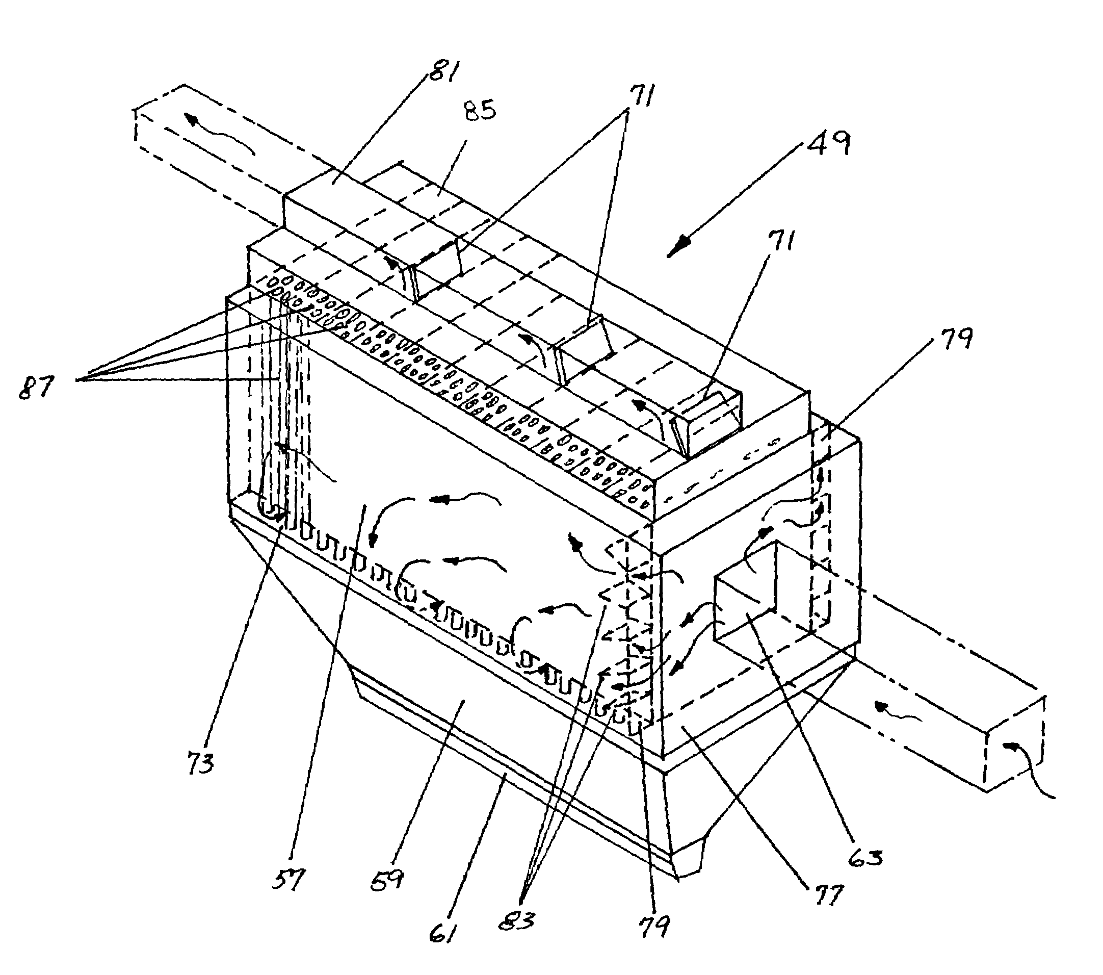
[0018]A primary object of the present invention is to improve upon the efficiency of currently accepted designs of bag house vessels regarding internal airflows, and to improve upon the effectiveness and efficiency of bag cleaning science. The present invention creates an airflow pattern in the bag house with a more stable velocity pattern. Inlet air enters the bag house and is initially subject to gravity removal of large particulate matter. This large particulate matter is directly guided to the hopper section of the apparatus. After heavy particulate has been initially filtered, the dirty inlet air is split into two plenums on either side of the house. This divided air is then passed through guide vanes that create favorable velocity profiles for entering the bag chamber. The change in velocity profile creates a more stable airflow through the bag section of the house.
[0019]The overall bag house structure must be altered in order to provide for more effective straight line air movements within each chamber of the bag house. In order to first eliminate internal turbulence and stabilize pressures and flow pathways, it is necessary to design dirty air inlets to “straighten the air” and distribute the volume evenly throughout the hopper and bag section of the house, eliminating turbulence and vortices. By entering at the center of a large (frontal entry) distribution chamber, inlet air is directed to both right and left sides of the bag house splitting the flow volume and allowing it to be evenly directed down and under the bags. A large inlet plenum stabilizes inlet air pressure and also acts as a “primary knock out box collector” to capture and eliminate larger sized dust particulates from the air stream and deposit the material directly into the hopper. Removing large particulates from the air stream prior to entering the bag section helps to reduce abrasive wear and increases bag life considerably. After the dirty air stabilizes within the hopper and bag section, it is evenly vacuumed up through the bags in a continuous vertical plane into the clean air plenum.
[0021]The present invention also incorporates a method referred to as “up-draft bag house pressure pulse” cleaning. The use of the novel up-draft pressure pulse bag cleaning system simplifies the bag cleaning operation by eliminating the need for high pressure, high volume requirements of compressed air as used with pulse jet cleaning systems. The elimination of compressed air from the cleaning system also eliminates the ongoing maintenance requirement of the solenoid diaphragm valves needed to pulse each row of bags as well as the cost and maintenance of an air compressor. By eliminating the need for compressed air cleaning from the system, the danger of collected condensation within the air piping system that could freeze and damage piping is also eliminated. This is a common problem as many industrial applications operate in below freezing temperatures.
[0022]The up-draft pressure pulse cleaning system of the present invention is a simple yet efficient method of allowing the inertia of the exiting air flow in the clean air plenum to be momentarily stopped and then reversed on a selected compartment of bags creating a slight pressure pulse or reversal of flow in the bag. The momentary pulse or flow directional change is sufficient to allow the bag cloth to relax on the cage and alter its dynamic shape. The filter bags that are recommended for use with the present pressure pulse cleaning systems are slightly oversized to allow the bags to more easily change shape from tight online (under vacuum) shapes to relaxed offline shapes. The moment that the bag changes its dynamic shape (under vacuum shape) to a relaxed posture, the dust cake on the outside of the bag will drop off. The bag is then returned to normal operating vacuum and re-assumes its dynamic shape once again.
[0023]The clean air plenum contains a series of individual compartments that have a pre-set number of bags that can be effectively cleaned during each cycle. Each of these individual compartments has a door or louver located at the top of each plenum that is opened and closed during the cleaning cycle. An automatic control system continuously senses bag house pressure drop and activates the cycle when cleaning is required. The doors open and close in a pre-set pattern to drop the dust cakes from the bags and restore air flow to normal pressures.
[0025]It is the combination of the uniquely directed and controlled up-draft internal air flows within the vessel that eliminate re-circulation, along with the increased cleaning efficiency of the pressure pulse system that encompass the intent of this invention.

Problems solved by technology

A portable bag house is limited in size by the availability of permits and the ability to transport the bag house on a highway.
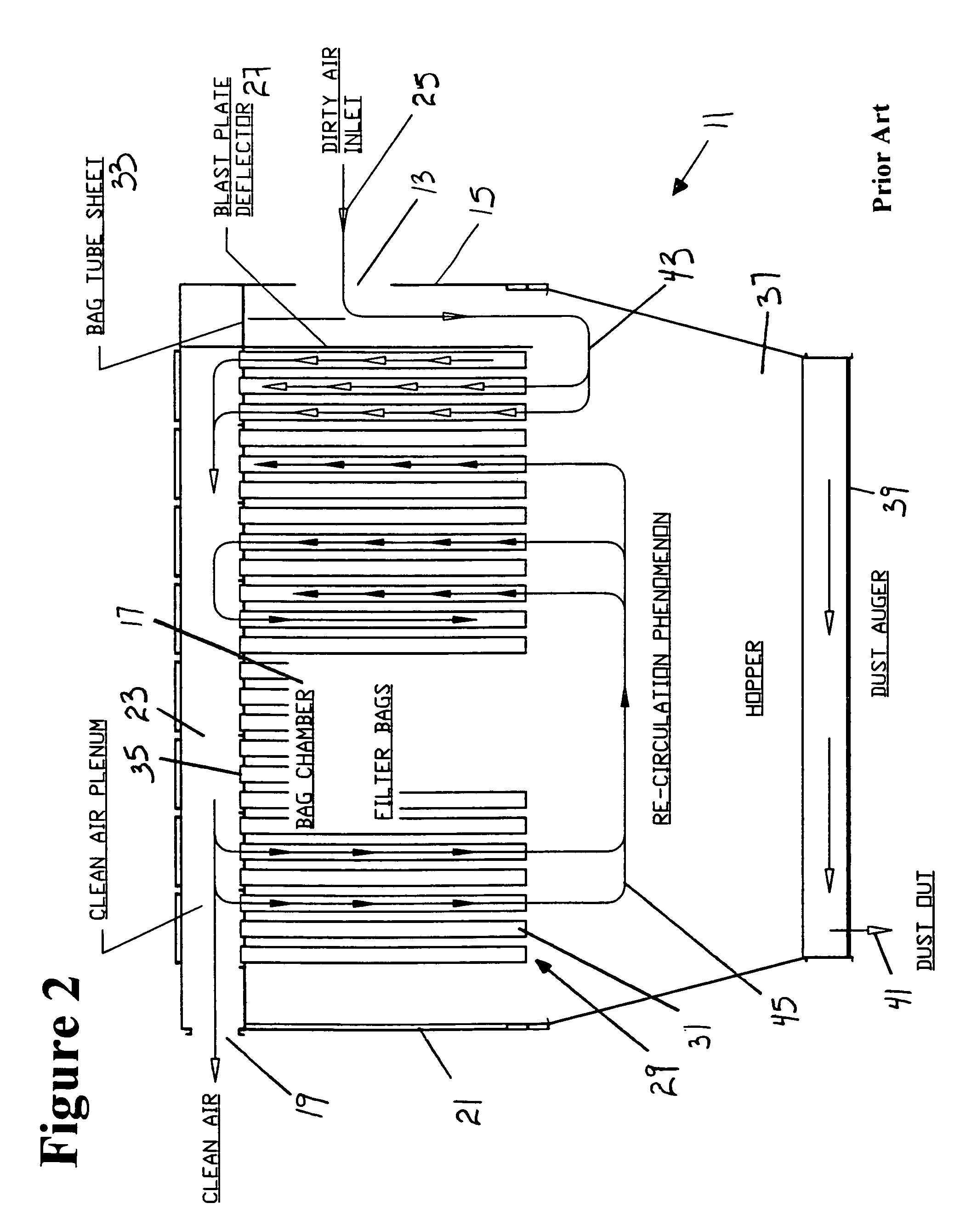
During the operation of a typical bag house, cleaned air is inadvertently recycled through the system.
However, when the clean air from the bags closest to the dirty air inlet passes over the filter bags near the clean air outlet of the system, some of the clean air is drawn back down into the filter bags and passes through the filter bags in the wrong direction.
This creates a re-circulation problem that reduces the efficiency of the bag house.
It has been determined that current methods of bag house design, as well as current methods of bag cleaning, are grossly inefficient.
Additionally, in some iristances the inefficiencies in bag house design and bag cleaning can lead to negative air effects that actually contribute to air emissions.
Because of the non-linear terms in these PDEs, analytic methods can yield very few solutions.
These bags do not contribute to the filtration process and can therefore only reduce bag house overall capacity while reverse flowing rather than online cleaning.
These periodic bursts of fine dust during bag house stack tests can result in failure to pass the particulate loading and opacity air tests.
This problem is relatively common with pulse jet type cleaning systems.
The flow field in the bag house is complex and highly three-dimensional.
This in turn can cause reverse flow through the bags.

Method used


Image

  • Modular up-draft pressure pulse bag house
  • Modular up-draft pressure pulse bag house
  • Modular up-draft pressure pulse bag house

Examples


Embodiment Construction

[0038]The present invention relates to the effective capture and removal of particulate material from dust laden air streams that must exit to atmosphere from many different process systems.

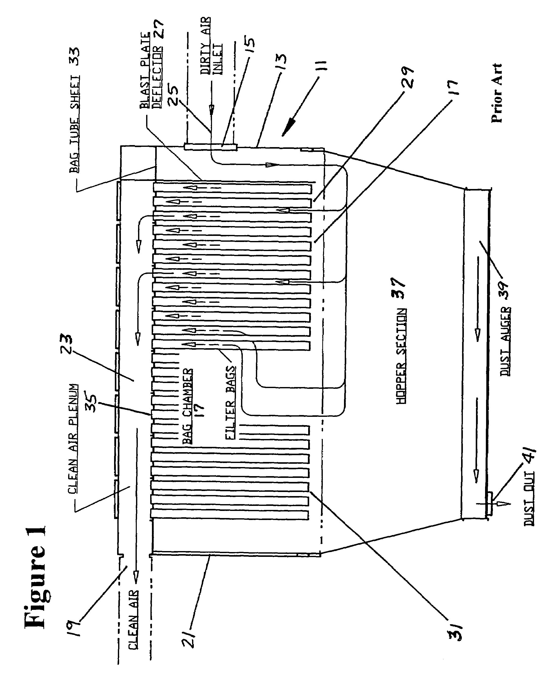
[0039]FIG. 1 shows a typical bag house 11. A standard bag house 11 consists of a vessel 13, generally a rectangular container, having a dirty air inlet on one end 15 leading into a lower bag section 17 with a clean air outlet 19 on the other end 21 at the top leading from the upper clean air section 23. Incoming dirty air 25 is deflected downward into the bag chamber 17 of the bag house 11 by a blast deflector plate 27. The blast deflector plate 27 also protects bag filters 29 from being damaged by the force of the incoming dirty air 25. After the dirty air 25 enters the bag chamber 17, it must pass thorough a set of bag filters 29 in order to reach the clean air outlet 19.

[0040]The bag house 11 contains a multitude of bag filters 29. Each bag filter 29 consists of woven fabric bags 31 that can b...


PUM

PropertyMeasurementUnit
pressureaaaaaaaaaa
gravityaaaaaaaaaa
velocityaaaaaaaaaa

Abstract

A bag house air filtration system with minimal recirculation uses new inlet airflow patterns and cleaning processes. Inlet air enters the bag house. An input plenum changes the velocity profile. Dirty inlet air is split into two plenums, and then passed through guide vanes. A clean air plenum contains a series of individual compartments with a pre-set number of filter bags that are effectively cleaned during a single cleaning cycle. Each individual compartment has a door or louver mounted above the bag openings that is opened and closed during the cleaning cycle. An automatic control system continuously senses bag house pressure drop and activates the cycle when needed. The doors open and close in a pre-set pattern to drop the dust cakes from the bags and restore air flow to normal pressures. Closing a door mounted above the bags creates a reversal of pressure that removes the dust cake.

Description

[0001]This application claims the benefit of U.S. Provisional Application No. 60 / 606,133, filed Sep. 1, 2004, which is hereby incorporated by reference in its entirety.BACKGROUND OF THE INVENTION[0002]The present invention relates to the effective capture and removal of particulate material from dust laden air streams that must exit to atmosphere from many different process systems. Process systems include such varied applications as power plants, process kilns, cement plants, grain processing plants, foundries, steel mills, hot mix asphalt plants and many other industrial processes.[0003]It is generally known and accepted throughout these industries that fabric filter collection systems (“bag houses”) provide the most economical and efficient “dry method” of removing small particulate material from process air streams. EPA air emissions laws governing the amount of particulate emissions allowed to exit into the atmosphere from any given process are now generally standardized throug...

Claims


Application Information

Patent Timeline
Patent Type & Authority Patents(United States)
IPC IPC(8): B01D46/00B01D29/66
CPCB01D46/0041B01D46/0057B01D46/04B01D46/66
Inventor COLLETTE, JERRY R.
Owner COLLETTE JERRY R
Learn More