Filter device for fluids and method for filtering fluids

a filter device and fluid technology, applied in gravity filters, loose filtering material filters, cartridge filters, etc., can solve the problems of wear due to such particles, and system ageing more quickly, so as to save costs and operate longer, the effect of longer working tim

Active Publication Date: 2009-01-20
RASSINGER GUENTHER
View PDF48 Cites 11 Cited by
  • Summary
  • Abstract
  • Description
  • Claims
  • Application Information

AI Technical Summary

Benefits of technology

[0009]The object of the invention is to make available a filter device and a method for filtering fluids, especially motor and hydraulic oils, which completely permits exploiting the storage capacity of the filter inserted into the filter device to hold water, particles and unwanted contaminants which greatly extends the service life of the filter.
[0018]The invention achieves advantages associated with the fact that the filter capacity for particles and contaminants is extensively exploited, including in particular the filter's capacity to absorb water, which results in the inventive filter device having a filter service life which, in comparison with filter assemblies containing identically large filters, for motor oils, are longer by at least a factor of greater than 1, preferably 2-3 times or larger, and for hydraulic oils, at least by a factor of greater than 1, preferably 2-3 times, or as great as 10 times. Correspondingly, the oil service life is also lengthened by the same or greater factors of the filter life. This enables motors, hydraulic systems and other machines lubricated with oils to be operated longer without filter and oil change. A major cost saving is thus achieved since neither the filter nor the oil must be changed as frequently which, in turn, permits longer working time.

Problems solved by technology

Particles such as these cause damage to engines, pumps, controls, regulators, so that such systems age more quickly due to mechanical wear and corrosion.
Even liquid media such as motor oil, transmission oil, hydraulic oil, transformer oil, petroleum and synthetic oils and mixtures, mineral oils, partially and completely biological oils or their mixtures, and completely synthetic oils cause wear due to such particles and become contaminated more quickly.
If the particles and contaminants are not filtered out, the systems can experience clogging or adhesive lock since the liquid media, such as the diverse oils specified above, can thicken due to accumulation of particles and / or the formation of an emulsion, i.e. its viscosity increases and, hence, a high degree of friction is created in lubricating slots, along crankshafts and at other moving machine parts.
30 μm are pulverized, the number of particles, i.e. the particle density, increases, resulting in the pulverized particles severely lowering the air release property of the oils, which in turn results in an acceleration of the oxidative corrosion and cavitation of the machine parts due to the oxygen contained in the oil.
Hence, for example, if the lubricating slot in a piston engine is not completely wetted or filled with oil, elliptic bulges are created which reduce engine performance and engine efficiency and lead to increased fuel and oil consumption as well as to increased exhaust emissions.
Pumps in the hydraulic system are subject to the same negative effects as engines.
Water can also enter the motor oil if the cylinder head seals leak or burst.

Method used


Image

  • Filter device for fluids and method for filtering fluids
  • Filter device for fluids and method for filtering fluids
  • Filter device for fluids and method for filtering fluids

Examples


Embodiment Construction

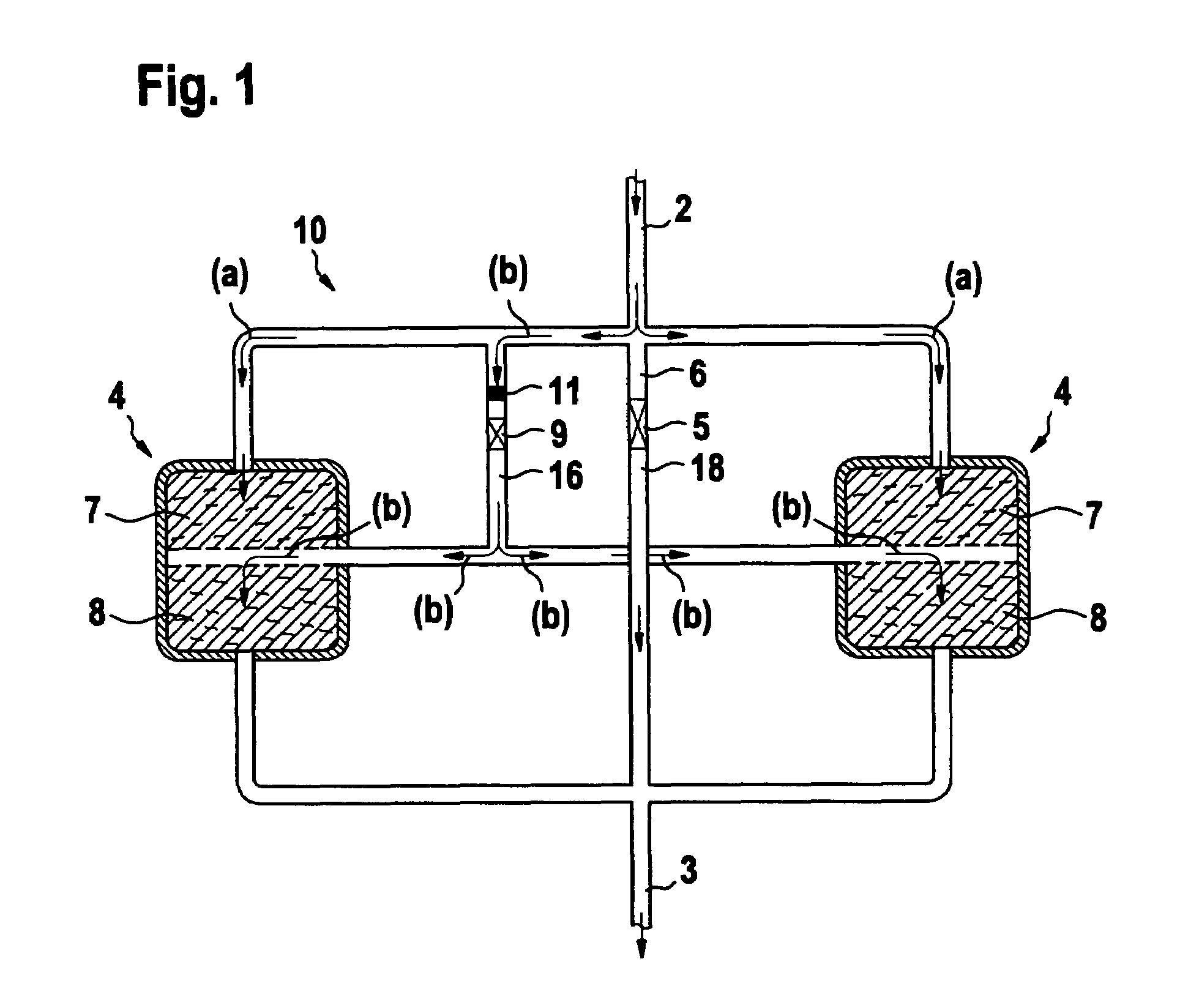
[0027]A filter device 10, shown schematically in cross-section in FIG. 1, is arranged in a closed circulation system which involves motor oil, hydraulic oil, other oil or other fluid, for an excavator, for example. Filter device 10 includes a filter inlet 2, a filter outlet 3 and an intermediary filter 4, consisting of an outer filter element 7 and an inner filter element 8. The filter elements 7, 8 are designed in a ring shape and arranged concentrically around a central tube 18 of a filter device 10. The intermediary filter 4 is schematically split up in two parts, each having the reference numeral 4, for better understanding the function of the filter device 10 as described thereafter. It is to imagine that one part is arranged left from the tube 18 and the other part of filter 4 is right from tube 18. A duct 16, in which a sieve 11 is positioned upstream from a pressure-controlled regulating valve 9, by-passes one part of filter 4, specifically the outer filter element 7, and ru...


PUM

PropertyMeasurementUnit
diameteraaaaaaaaaa
diameteraaaaaaaaaa
temperatureaaaaaaaaaa

Abstract

A filter device 10 for fluids, especially for motor oil, hydraulic oil, has a filter case 1 comprising one or two filter inlets 2 and one filter outlet 3. The filter case contains one filter 4 consisting of at least two ring-shaped filter elements 7, 8 which concentrically enclose a central tube 18 of the filter device. In a channel 14 between the two adjacent filter elements there is a duct 16 which is run in the form of a spiral around inner filter element 8 and is embedded in filter 4. In duct 16 there is a pressure-controlled regulating valve 9 which opens when a certain level of pressure is exceeded in the filtered oil.

Description

BACKGROUND OF THE INVENTION[0001]1. Field of the Invention[0002]The invention relates to a filter device for fluids, including a filter case containing at least one filter inlet and one filter outlet and one filter arranged in between. The device includes a duct for by-passing a portion of the filter, and a valve for by-passing the entire filter. The invention also relates to a method for filtering fluids through a filter, including the steps of introducing a fluid, filtering the fluid until the pressure across the filter reaches a first limit, by-passing a portion of the filter while continuing filtering the fluid, and by-passing the filter entirely when the pressure across the filter reaches a second limit. The first and second limit may be the same or different.[0003]2. Prior Art[0004]Particles of various sizes and consistency which collect in liquid and gas media used for lubricating and / or cooling moving machine parts as a result of wear, corrosion, contamination and related co...

Claims


Application Information

Patent Timeline
Patent Type & Authority Patents(United States)
IPC IPC(8): B01D35/147
CPCB01D29/114B01D35/147B01D29/54B01D29/58
Inventor RASSINGER, GUENTHER
Owner RASSINGER GUENTHER
Why Eureka
Try Eureka