
Optical scanner device

a scanning device and optical scanner technology, applied in the direction of instruments, optical elements, discharge tubes/lamp details, etc., can solve the problem of distorted image generated based on reflection which is not accurately controlled, and achieve the effect of higher accuracy

Inactive Publication Date: 2009-01-20
HOYA CORP
View PDF15 Cites 3 Cited by
  • Summary
  • Abstract
  • Description
  • Claims
  • Application Information

AI Technical Summary

Benefits of technology

The present invention provides an optical scanner device with a detecting unit that can accurately position the light source to detect the position of a light spot on an observation object. This device includes an objective lens system that focuses the light source on the observation object, a photo-detector unit that detects the position of the light spot, and a controlling system to adjust the position of the light source to the detected position. The device can be used in various applications such as optical scanning, laser scanning, and light detection. The technical effects of this invention include improved accuracy in position detection and improved efficiency in optical scanning.

Problems solved by technology

Therefore, a problem occurs as such the image generated based on reflection which is not accurately controlled is distorted when the inclination angle of the mirror surface is greater.

Method used


Image

  • Optical scanner device
  • Optical scanner device
  • Optical scanner device

Examples


first embodiment

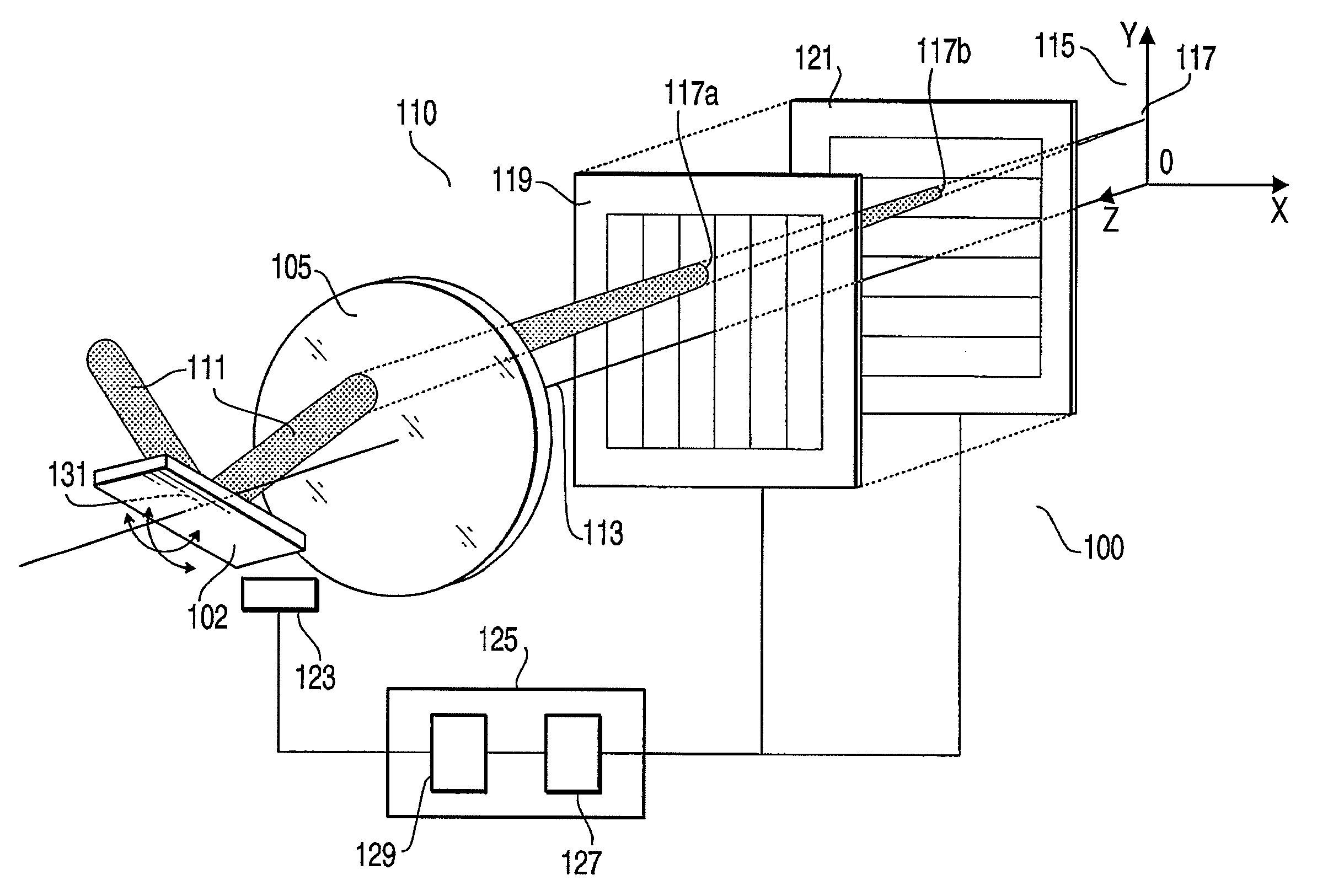
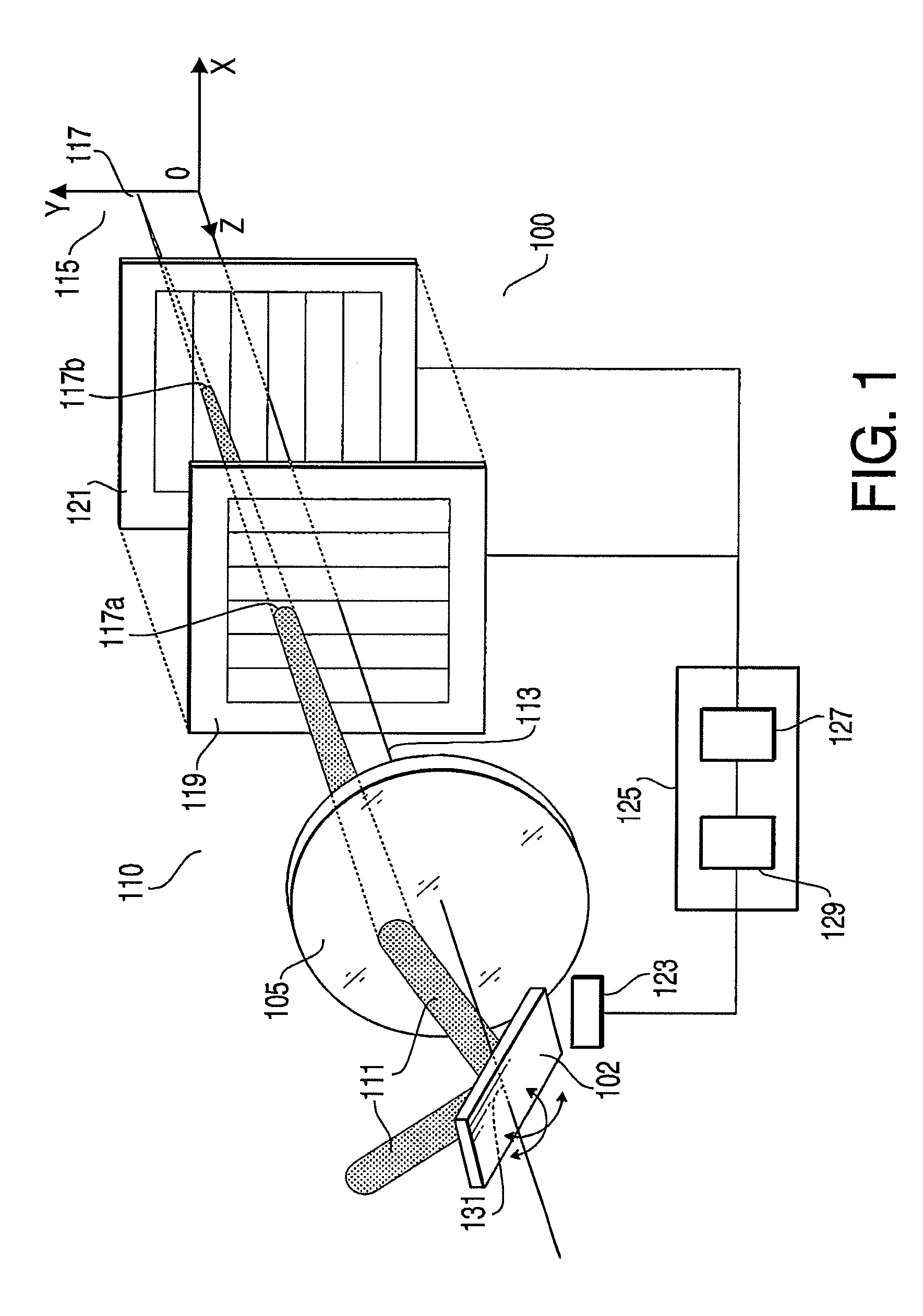
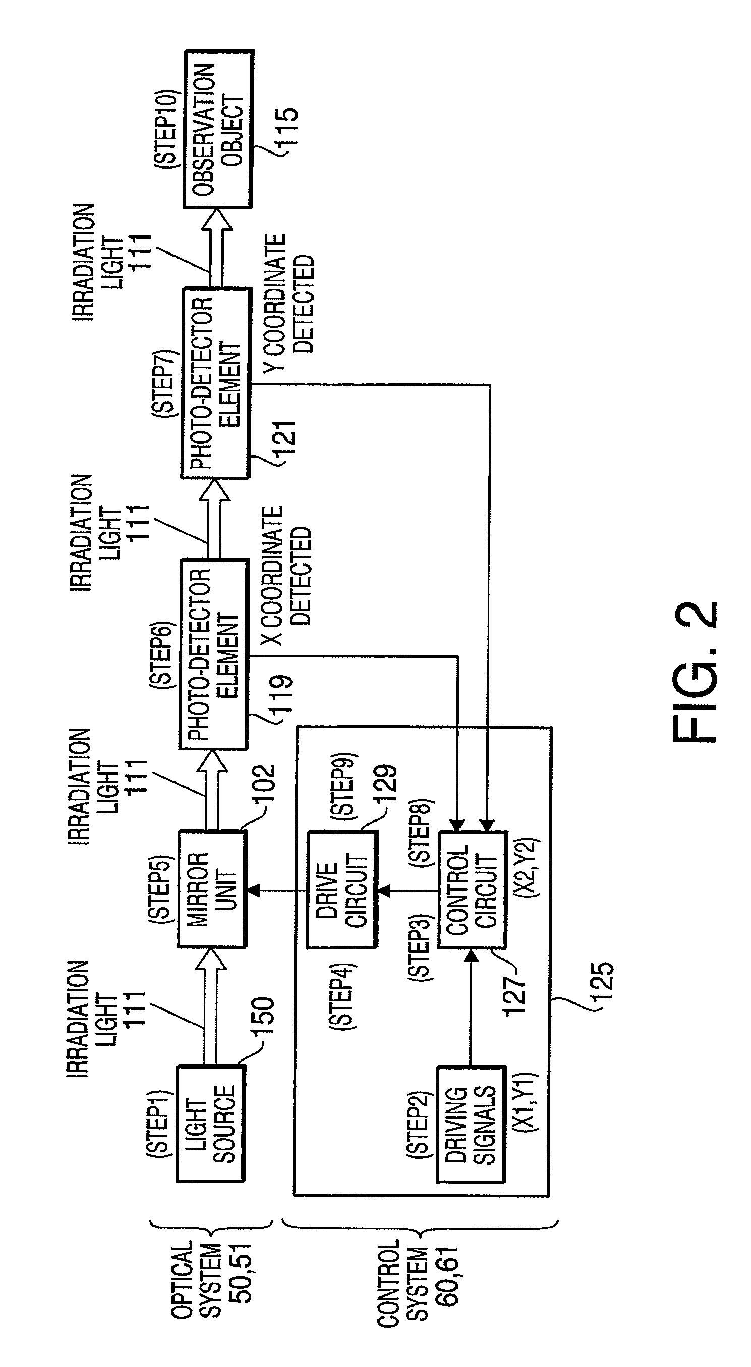
[0045]FIG. 1 shows an optical scanner device 100 with photo-detector elements arranged on an optical axis thereof according to a first embodiment of the present invention. The optical scanner device 100 includes an optical system 50 and a control system 60 (see FIG. 2). The optical system 50 includes a light source 150, a mirror unit 102, a light spot position detector unit 110. The control system 60 includes a control unit 125. The light spot position detector unit 110 is provided with an objective lens system 105, a photo-detector element 119, and a photo-detector element 121. It should be noted that an optical axis of the objective lens system 105 is also referred to as an optical axis 113 of the optical scanner device 100.

[0046]The mirror unit 102, the objective lens system 105, the photo-detector element 119, and the photo-detector element 121 are respectively arranged on the optical axis 113. In the optical scanner device 100, irradiation light 111 such as laser beam supplied ...

second embodiment

[0062]Next, an optical scanner device 200 to obtain a position of a light spot based on a polar coordinate system (r, θ) according to a second embodiment of the present invention will be described.

[0063]FIG. 5 shows an optical scanner device 200 with photo-detector elements arranged on an optical axis thereof according to a second embodiment of the present invention. In the present embodiment, description of a configuration being similar to the configuration described in the first embodiment will be omitted. The optical scanner device 200 includes an optical system 51 (see FIG. 2) having an optical fiber unit 201, a light spot position detector unit 210, and a control system 61 (see FIG. 2) having a control unit 225. The light spot position detector unit 210 includes an objective lens system 205, a photo-detector element 219, and a photo-detector element 221. It should be noted that an optical axis of the objective lens system 205 is referred to as an optical axis 213 of the optical...


PUM


Abstract

An optical scanner device, comprising a scanning unit, which casts irradiation light emitted from a light source in an arbitrary direction to scan an observation object, an objective lens system, which converges the irradiation light on the observation object, and a photo-detector unit, which is disposed on an optical axis of the objective lens system to have the irradiation light transmit therethrough, is provided. A position of the irradiation light converged on the observation object is detected based on a position of a light spot of the irradiation light transmitting through the photo-detector unit.

Description

CROSS-REFERENCE TO RELATED APPLICATION[0001]This is a continuation-in-part of International Application PCT / JP2005 / 019667, with an international filing date of Oct. 26, 2005, the contents of which are expressly incorporated herein by reference in its entirety.BACKGROUND OF THE INVENTION[0002]The present invention relates to a small-type optical scanner device having a photo-detector unit capable of accurately detecting a position of a light spot.[0003]Conventionally, a confocal probe device having an optical scanner unit and a confocal optical system has been known. The optical scanner unit can cast irradiation light (for example, laser light) emitted from a light source onto an observation object and is adapted to scan the observation object by being driven by a drivable optical fiber and an electrostatically-actuated mirror. The confocal optical system receives the light scanned and reflected on a focal plane of the observation object and eventually generates a confocal image of t...

Claims


Application Information

Patent Timeline
Patent Type & Authority Patents(United States)
IPC IPC(8): H01J3/14
CPCG02B21/0048G02B26/101G02B26/127
Inventor KARASAWA, SATOSHIMIZUNO, JUN
Owner HOYA CORP
Learn More