Relative drive device

a technology of relative drive and drive shaft, which is applied in the direction of motor/generator/converter stopper, electronic commutator, dynamo-electric converter control, etc., to achieve the effects of smooth operation, high efficiency, and no iron loss

Inactive Publication Date: 2009-01-20
TAKASHI KENJO +1
View PDF14 Cites 9 Cited by
  • Summary
  • Abstract
  • Description
  • Claims
  • Application Information

AI Technical Summary

Benefits of technology

[0009]Since this relative drive device does not have a magnetic-material core, and therefore allows for smooth and stable relative driving, without producing cogging. Moreover, because the device has substantially no magnetic-material yoke, a highly efficient relative drive device can be realized, having almost no iron loss (eddy current loss).
[0011]This construction also allows for the realization of a highly efficient relative drive device having substantially no iron loss, and capable of smooth, stable operation, without generating cogging torque.

Problems solved by technology

However, conventional transmission systems are able to transmit driving force in only one predetermined direction from one drive shaft to another drive shaft.

Method used


Image

  • Relative drive device
  • Relative drive device
  • Relative drive device

Examples


first embodiment

A. First Embodiment

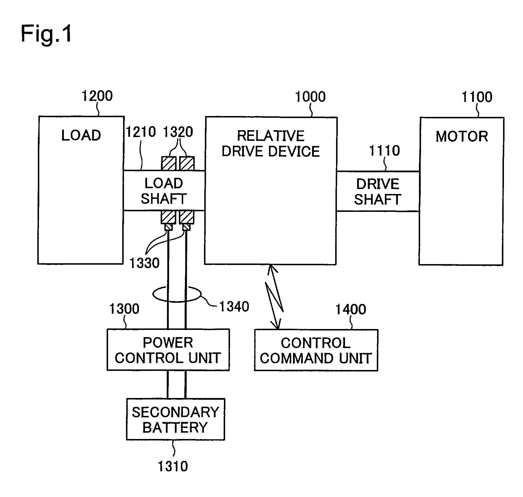
[0041]FIG. 1 is a block diagram illustrating a drive system according to a first embodiment of the present invention. This system comprises a relative drive device 1000, a motor 1100, a load 1200, a power control unit 1300 and a control command unit 1400. The power control unit 1300 is connected to a secondary battery 1310.

[0042]An internal combustion engine or an electric motor can be used as the motor 1100. The load 1200 may, for example, take the form of the wheels of an automobile. The motor 1100 and the relative drive device 1000 are interconnected by the drive shaft 1110. The relative drive device 1000 and the load 1200 are interconnected by a load shaft 1210. DC power contacts 1320 are provided on the load shaft 1210. The contacts 1320 are connected to a drive control circuit unit (described hereinbelow), which is internal to the relative drive device 1000. The contacts 1320 are also connected to the power control unit 1300 by way of brushes 1330 and power ...

second embodiment

B. Second Embodiment

[0093]FIGS. 14A and 14B are cross-sectional views illustrating a second embodiment of the relative drive device 1001. This relative drive device 1001 is such that, in the device of the first embodiment shown in FIG. 3, a governor mechanism 90 is provided between the support member 32M for the magnet group 34M and the bearing 38, the rest of the structure being the same as in the first embodiment. The governor mechanism 90 comprises a spring 92 for urging the support member 32M for the magnet group 34M to the left in the drawing.

[0094]As shown in FIG. 14A, during low-speed rotation, the support member 32M for the magnet group 34M is maintained in a position pressed against a stopper 33 by the spring 92 of the governor mechanism 90. This state is substantially identical to the state shown in FIG. 3A. However, during high-speed rotation, as shown in FIG. 14B, the centrifugal force of the governor mechanism 90 compresses the spring 92 so that the support member 32M f...

third embodiment

C. Third Embodiment

[0096]FIG. 15 is a sectional view illustrating a relative drive device 1002 according to a third embodiment. This relative drive device 1002 is such that, starting from the device according to the second embodiment shown in FIGS. 14A and 14B, the positioning of the coil groups 14A and 24B is changed so that the facing inner circumferential faces of the coil groups 14A and 24B are both tapered, and the sections of the magnets in the magnet group 34M are also tapered in a corresponding manner.

[0097]This relative drive device 1002 also comprises a governor mechanism 90 for changing the magnetic coupling between the coil groups 14A and 24B and the magnet group 34M. Accordingly, when the speed of revolution increases, the magnet group 34M moves to the right in the drawing so as to weaken the magnetic coupling between the coil groups 14A and 24B and the magnet group 34M. In particular, in the third embodiment, if the magnet group 34M moves to the right in response to in...


PUM


Abstract

A small, lightweight relative drive device is provided, which is capable of producing large torque. The relative drive device of a two-phase magnetic excitation type according to an aspect of the invention comprises first and second coil groups and a magnet group. The magnet group includes magnets disposed with alternating north and south poles facing the first and second coil groups. The first and second coil groups are disposed at positions that are out of phase with each other by an odd multiple of π / 2 in electrical angles. The coils in the first and second coil groups have substantially no magnetic material cores, and the relative drive device has substantially no magnetic material yoke for forming a magnetic circuit.

Description

CROSS REFERENCE TO RELATED APPLICATIONS[0001]The present application claims the priority based on Japanese Patent Application No. 2004-147130 filed on May 18, 2004, the disclosure of which is hereby incorporated by reference in its entirety.BACKGROUND OF THE INVENTION[0002]1. Field of the Invention[0003]The present invention relates to a device for driving two driving force transmission members relative to each other, using electrical energy.[0004]2. Description of the Related Art[0005]Various transmission systems are known as devices for driving two drive shafts relative to each other (for example, JP-2001-124163-A).[0006]However, conventional transmission systems are able to transmit driving force in only one predetermined direction from one drive shaft to another drive shaft. Furthermore, in order to recover electrical power by so-called regeneration, it is necessary to provide a separate motor.SUMMARY OF THE INVENTION[0007]An object of the present invention is to provide a novel...

Claims


Application Information

Patent Timeline
Patent Type & Authority Patents(United States)
IPC IPC(8): H02K47/04F16H61/02B60L50/16H02K16/04H02P7/00H02P27/06H02P27/08
CPCH02K16/005H02K16/04H02K21/027H02P6/16H02K21/024H02P2207/03
Inventor TAKEUCHI, KESATOSHIKENJO, TAKASHIKAJI, KOBUFUJI
Owner TAKASHI KENJO
Why Eureka
Try Eureka